Franklin Fueling Systems TS-DTU Data Transfer Unit Dispenser Retrofit Manual User Manual
Page 30
30
Wayne Vista 1 - DTU Installation
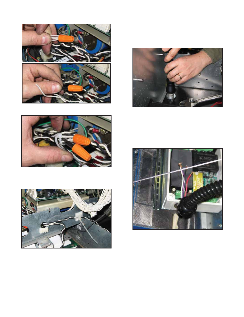
25. Using wire nuts provided, connect all three white
wires together. Connect three black wires together.
Figure 10: Connect Wires
26. Use tie-wrap to attach connections together.
Figure 11: Wrap Wires
27. Attach wiring from power wiring harness to the
side of the display assembly using adhesive
backed anchor and wire tie.
Figure 12: Attach Power Wiring Harness
28. Close display assembly and fi rmly attach using
two screws. Ensure that all wiring is free of sharp
edges and pinching when doors close. If sharp
edges or pinching is observes, use additional tie
wraps and anchors to reroute wiring as necessary.
29. Attach ring terminal of ground wire to dispenser
bracket using screw and nut as shown. Wind
excess wiring and fi rmly attach with tie wraps to
ensure that it does not interfere with door closing.
30. Find straight conduit fi tting and fl exible conduit
from IS conduit kit, 020-1513. Remove nut and
bushing from straight conduit fi tting. Push bushing
on one end of fl exible conduit. Pull wires from
nipple assembly through bushing / fl exible conduit
and attach fl exible conduit to straight conduit fi tting
using nut.
Figure 13: Attach Flexible Conduit
31. Remove nut and bushing from the 90-degree
conduit fi tting and feed fl exible conduit through
nut. Put bushing on unattached end of fl exible
conduit. Pull wires from fl exible conduit through
the 90-degree conduit fi tting and pull excess wire
into DTU. Use nut to attach fl exible conduit to
90-degree fi tting.
Figure 14: Flexible Conduit DTU Connection
32. Cut excess wire inside DTU allowing a length of 2”
for terminal block wiring. Strip wire insulation 3/8”
from the end of the wire.