Dispenser specifi c installation – Franklin Fueling Systems TS-DTU Data Transfer Unit Dispenser Retrofit Manual User Manual
Page 7
7
General Information
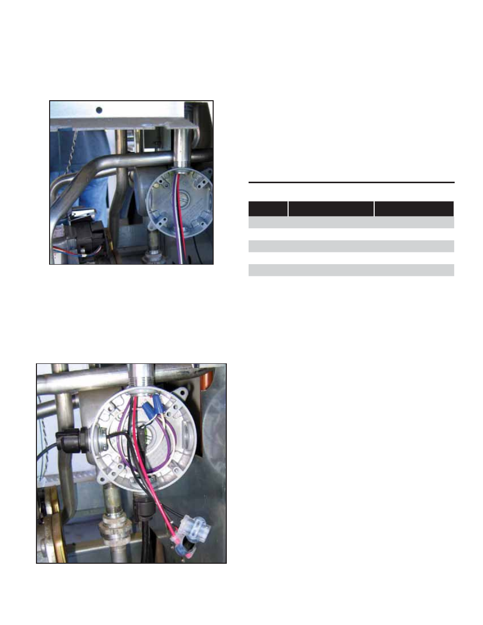
Connecting the Vapor Flow Meter and Vapor
Pressure Sensor
The connection of potted nipple to the TS-VFM and TS-
VPS in the lower section of the dispenser is the same for all
dispensers. For ease of installation, a junction box may be
connected directly to the bottom of the potted nipple. Note,
the potted nipple is a ¾” conduit thread, see Figure 8.
Figure 8: Junction Box Connected to Potted Nipple
TS-VFM Splice
1. Find two-splice connectors in the IS Wiring Kit, 020-
1513.
2. Make the following splice connections:
• Red wire of potted nipped to Red wire of TS-VFM
cable.
• Black wire of potted nipple to Black wire of TS-VFM
cable.
Figure 9: VFM and VPS Spices
TS-VPS Splice
1. Find two wire nuts in the Power Harness Kit, 600-
016X.
2. Make the following splice connections:
• Purple wire of potted nipped to Black wire of TS-
VPS cable.
• White wire of potted nipple to White wire of TS-VPS
cable (Refer to Figure 9).
Dispenser Specifi c Installation
This manual covers the following types of dispensers:
Make
Type
Installation Kit
Gilbarco
Advantage
TS-DRK/A
Encore 300 & 500
TS-DRK/E
Tokheim
Premier B
TS-DRK/T
Tokheim Premier
C
TS-DRK/T
Wayne
Ovation
TS-DRK/W
Vista 1V, 2V, 3V
TS-DRK/W
Table 1: Dispenser Kits