Franklin Fueling Systems TS-DTU Data Transfer Unit Dispenser Retrofit Manual User Manual
Page 31
31
Wayne Vista 1 - DTU Installation
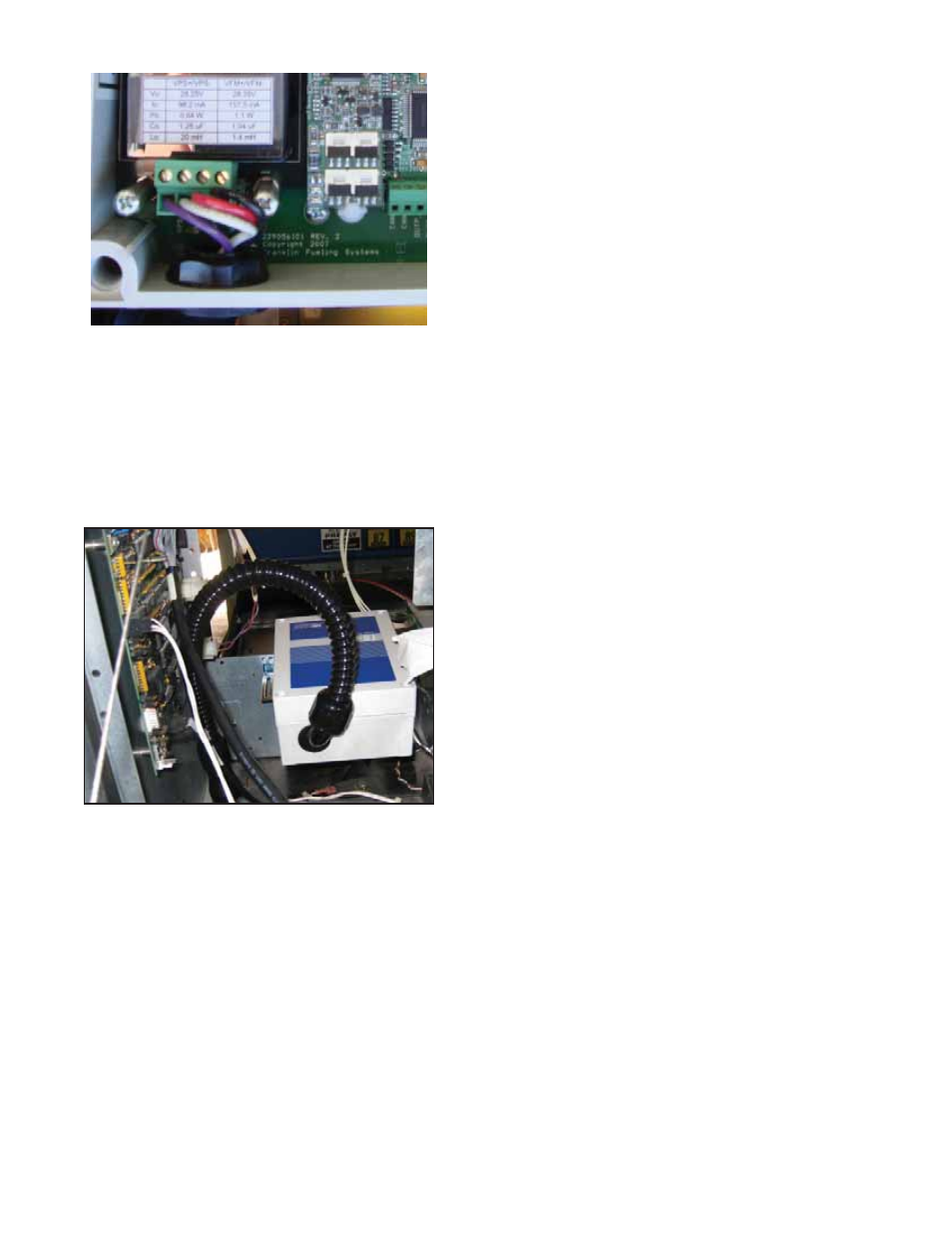
33. Attach wires to DTU terminal block as follows
Figure 15: Wires Connected to DTU
34. Reinstall barrier cover using screws that were
removed in step 20.
35. Replace DTU cover.
36. Install the DTU assembly on the horizontal cross
bracket as shown in Figure 16. Use the two
screws, washers, and nuts as supplied in the TS-
DTU/P hardware kit. Take care that the fl exible
conduit does not interfere with the electronics on
the side of the dispenser.
Figure 16: DTU Installed with Cover On
Note: Moving the 90-degree conduit fi tting on DTU
slightly away from the dispenser PCB board will aid
in separating the conduit from the that board.
37. Find cable assembly extending from TS-VFM
vapor meter in dispenser hydraulics enclosure.
38. Find wiring from previously installed potted nipple
assembly inside hydraulics enclosure.
39. Find two wire splice connector kits. Inside
hydraulics enclosure, connect black wire from
potted nipple assembly to black wire from TS-VFM
fl ow meter by placing each lead into an opening in
the wire splice connector and push fi tting closed to
lock.
40. Locate cable extending from TS-VPS inside
hydraulics enclosure. Cut yellow and blue leads
from end of cable.
41. Find purple and white wires from potted nipple
assembly in hydraulics enclosure. Strip wire
insulation 3/8” from the end of the wire.
42. Using wire nuts provided with kit, attach purple
wire from potted nipple assembly to black wire
of TS-VPS. Attach white wire from potted nipple
assembly to white wire of the TS-VPS.
43. Reinstall lower hydraulic door using key-lock
44. Reinstall all connectors removed in step 3 & 4.
45. Close the bezel on the dispenser and secure using
two thumb screws from each side of the bezel.
46. Repeat steps 44 & 45 for the opposite side of the
dispenser.