Mounting and cabling specifications, Electrical box cutout, Panel mount cutout templates – Extron Electronics MKP 3000 Series User Manual
Page 53: Reference information, cont’d
MKP 3000 Series • Reference Information
MKP 3000 Series • Reference Information
Reference Information, cont’d
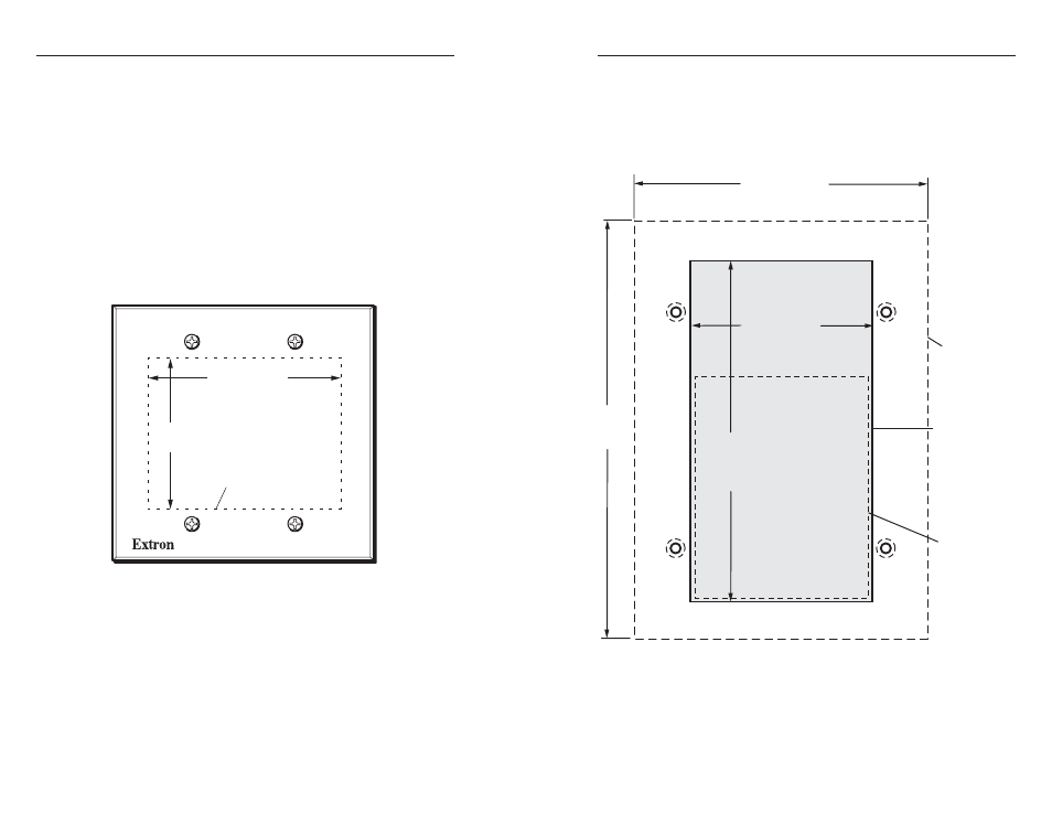
Figure A-2 shows the dimensions for cutting a hole to
accommodate the keypad circuit board for mounting an
MKP 3000 MAAP on a flat surface.
Figure A-2 — MKP 3000 MAAP panel mount cutout
template
A-7
Mounting and Cabling Specifications
Electrical box cutout
Any standard box that meets the local electrical codes can be
used, but boxes from different manufacturers may have
different size openings. Extron recommends testing the fit of
the MKP inside the electrical box and then placing the box flush
against the mounting surface and tracing the cutout area.
Panel mount cutout templates
Figure A-1 shows the dimensions for cutting a hole to
accommodate the keypad circuit board for mounting an
MKP 3000 on a flat surface. This type of installation can include
a desk or podium, or a control panel or dashboard, where the
back is protected and does not require an electrical box.
MKP 3000
VOLUME
I/O
2.63"
(6.68 cm)
3.38" (8.59 cm)
TEMPLATE IS NOT FULL SIZE
Circuit Board Box
(behind front panel)
Cut-out area should be slightly
larger.
Figure A-1 — MKP 3000 panel mount cutout template
A-6
VO
L
U
M
E
I/O
4.5" (11.43 cm)
6.4"
(16.26 cm)
Location of
Circuit Board
Box
2.75” (7.0 cm)
5.4”
(13.7 cm)
Cut-Out Template
For MKP 3000 MAAP
TEMPLATE IS NOT FULL SIZE.
SURFACE
CUT-OUT AREA
FOR WALL MOUNT
Recommended
cut-out area for
the installation
surface
Top Panel