Operation, cont’d – Extron Electronics MKP 3000 Series User Manual
Page 36
MKP 3000 Series • SIS
™
Operation
MKP 3000 Series • SIS
™
Operation
SIS
™
Operation, cont’d
4-13
4-12
Command/r
esponse table for MKP SIS commands (continued)
Command
ASCII Command
Response
Additional description
(host to
M
K
P
)
(M
K
P
to host)
P
reset names
P
resets must be named in the MKP 3000 for them to be r
ecalled fr
om the fr
ont panel.
Name a preset
Esc
X1
7
,
X1
6
NG
Nmp
X1
7
•
X1
6
Name preset
X1
7
“
X1
6
“.
Example
:
Esc
7
,
Staf
f mtg 3NG
NmpStaf
f mtg 3•
P
C
1
Name input 1 “Staff mtg 3”.
Read a pr
eset name
Esc
X1
7
NG
X1
6
P
reset
X1
7
is
named
“
X1
6
“.
Tie mode
Select matrix mode
0
*
2 #
Tmd 0
Select matrix (the default) as the tie mode.
Select input-only mode
1
*
2 #
Tmd 1
Select input-only as the tie mode.
V
iew the tie mode
2 #
X2
9
V
iew the curr
ent tie mode. For
X2
9
:
0 = matrix mode.
1 = input-only mode.
Disable/enable inputs and outputs
Enable all inputs
Esc
+
7BM
Upl
Enable all inputs.
Disable all inputs
Esc
+
6BM
Upl
Disable all inputs.
Enable all outputs
Esc
+
9BM
Upl
Enable all outputs.
Disable all outputs
Esc
+
8BM
Upl
Disable all outputs.
Read enables for up to 125 inputs
Esc
+
1BM
data (see below)
Display a list of which inputs ar
e enabled (available
for selection) or disabled (unavailable for selection).
Example
(for 16-input switcher)
:
Esc
+1BM
%5B%FF%01%00%00%00%00%00%00%...%00%00%00%
In this example, inputs 2, 5, and 7 ar
e disabled.
A
ll
other
valid
inputs ar
e enabled. Inputs 17 thr
ough
999 are
invalid
selections for a 16-input matrix
switcher
. See the
Data description
for the read
outputs command for a detailed explanation.
Command/r
esponse table for MKP SIS commands (continued)
Command
ASCII Command
Response
Additional description
(host to
M
K
P
)
(MKP t
o
host)
Disable/enable inputs and outputs, continued
Read enables for up to 125 outputs
Esc
+
5BM
data (see below)
Display a list of which outputs ar
e enabled or
disabled.
Example
(for 32-output switcher)
:
Esc
+5BM
%FE%FF%FF%FF%01%00%00%00%00%...%00%00%00%
In this example, all outputs are enabled. Outputs
33 through 999 ar
e
invalid
selections for a 32-
output matrix switcher
. See the
Data description
,
below
, for a detailed explanation.
The example below
, shows the content of the returned data for
either
a
r
ead of input enables
or
a r
ead of output enables.
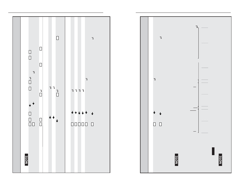
Data description
:
125 bytes of data; each bit in a byte shows if an input or output is enabled (if set to 1) or disabled
(if set to 0).
7
Inp
u
t or o
u
tp
u
t n
u
m
b
er
:
En
ab
le (1) or
di
sab
le (0)
Inp
u
t 7 or o
u
tp
u
t 7 en
ab
led.
NO
TE
E
a
ch
b
yte i
s
ret
u
rned mo
s
t-
s
ignific
a
nt
b
it fir
s
t (
su
ch
as
inp
u
t 7 in
b
yte 0), le
as
t-
s
ignific
a
nt
b
it l
as
t (
su
ch
as
inp
u
t 0 in
b
yte 0).
Byte
s
a
re ret
u
rned in
s
eq
u
enti
a
l order (
b
yte
, 0,
b
yte 1,
b
yte 2,...
b
yte 124).
6 5 4
3
2 1 0
15
14
1
3
1 1 1 1 1 1 1
n
1 1 1 1 1 0 0 1
1 1 1 1 1 1
12 11
10
9
8
2
3
22 21 20 19 1
8
Input
0 i
s
al
wa
y
s
1
(en
ab
led
).
Output
0 i
s
al
wa
y
s
0 (di
sab
led).
Byte delimeter
Inp
u
t 9 or o
u
tp
u
t 9 di
sab
led.
He
x:
46
Byte 0
Byte 1
Byte 2
46 or 45
25
25
A
S
CII:
F
F or E
%
%
0
0 0
0
0
0
0
0
99
8
997 996 995
Byte 124
999 994
99
3
992
3
0
3
0
0 0
46 46
F F
46
3
9
F 9
...
Input and output enables
can
be r
ead using SIS commands, but the returned data is hard to interpr
et. Reading the enabled outputs is far
simpler using the HTML pages. See “System Settings page” in chapter 5, “HTML Operation.”