Setting the lcd window backlighting, Setup procedures diagram, Local operation, cont’d – Extron Electronics MKP 3000 Series User Manual
Page 27
MKP 3000 Series • Local Operation
MKP 3000 Series • Local Operation
Local Operation, cont’d
SELECT
SELECT
IP 192.168
add 254.253
>
IP 192.168
add 254.253
>
IP 192.168
add 254.253
>
IP 192.168
add 254.253
IP 192.168
add 254.253
>
>
Sub 255.255
net 000.000
>
Sub 255.255
net 000.000
>
Sub 255.255
net 000.000
Sub 255.255
net 000.000
>
>
Gate 000.000
way 000.000
>
Gate 000.000
way 000.000
>
Gate 000.000
way 000.000
Gate 000.000
way 000.000
>
>
Host 000.000
IP 000.000
>
Host 000.000
IP 000.000
>
Host 000.000
IP 000.000
Host 000.000
IP 000.000
>
>
Passthrough
Disabled
>
Passthrough
Enabled
>
Connection
Primary
>
Connection
Secondary
>
SELECT
Backlight
30 Seconds
SELECT
INPUT
INPUT
INPUT
INPUT
INPUT
INPUT
INPUT
INPUT
TAKE
TAKE
OUTPUT
OUTPUT OUTPUT
OUTPUT OUTPUT
OUTPUT OUTPUT
OUTPUT OUTPUT
INPUT
>
Tie Mode
Matrix
>
>
Tie Mode
Input Only
The LCD shows MKP 3000’s
IP address. The caret (>)
shows the editable octet.
Press and hold these buttons for
2 seconds until they light amber.
This knob changes the
editable octet/field.
MKP 3000’s
IP Address
MKP 3000’s
Subnet Mask
MKP 3000’s
Gateway
Address
Matrix
Switcher’s
IP Address
Connection
Priority
Backlight
Duration
Host Control
Setting
2
Press button or rotate
the Select knob to toggle
between the Enabled and
Disabled selections.
Press button 3 to cycle through the
selected ( > ) and editable octets.
3
Press button or rotate
the Select knob to toggle
between the Primary and
Secondary selections.
Rotate the Select knob to
set the LCD backlight to
always on (0) or to timeout
after 001 to 255 seconds.
Press and release button to execute
all of the settings and exit Set-up mode.
Press b
utton 3 to cycle through the displa
y
e
d and
editab
le addresses and to reach the MKP setup settings
.
2
4
3
4
Tie Mode
SELECT
OUTPUT
OUTPUT
Press button or rotate
the Select knob to toggle
between the Matrix and
Input Only selections.
3
3
3
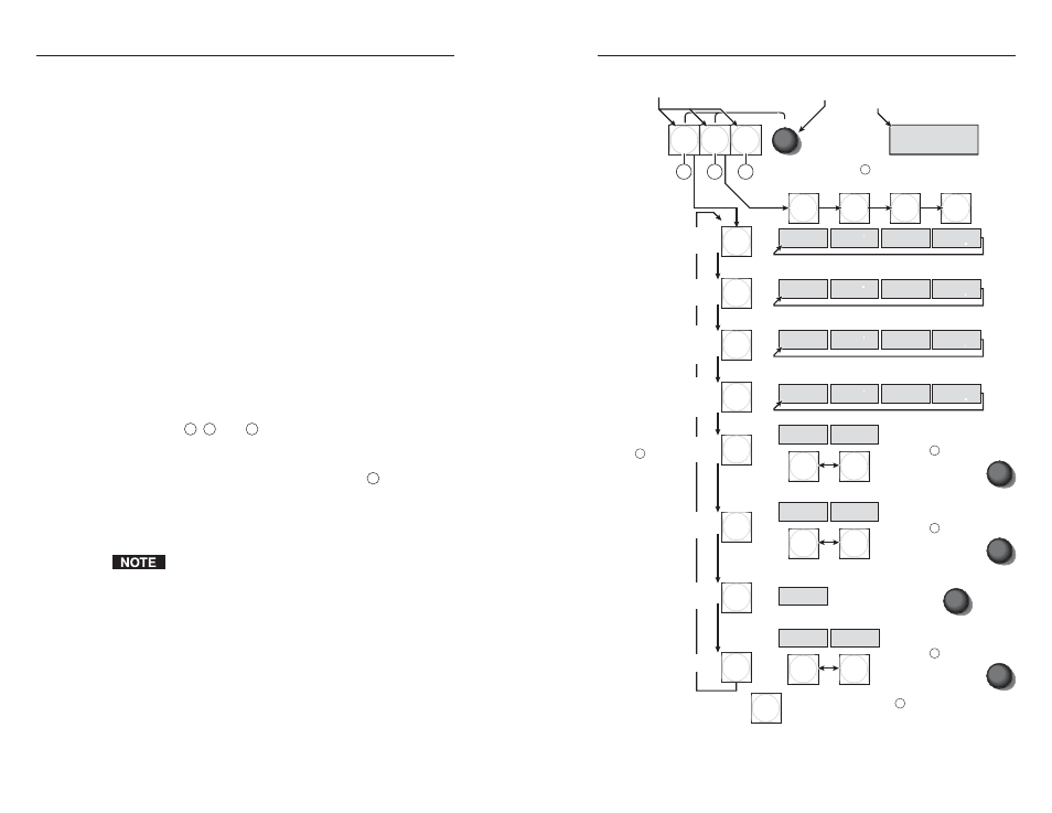
Figure 3-7 — Selecting setup parameters
3-15
When the MKP is
•
Connected to a computer or control system via its Host
RS-232 port and
•
In no pass-through mode,
the MKP acts on all valid MKP commands received. It does not
pass the command to its Switcher RS-232 port.
When the MKP is
•
Selected as primary:
The MKP directly controls the matrix switcher via its
Switch RS-232 port or LAN port
•
Selected as secondary:
The MKP controls the matrix switcher through
connection to the primary MKP’s IP address
Setting the LCD window backlighting
You can use the front panel buttons to specify the amount of
seconds that the MKP’s LCD display will remain backlit after a
front panel operation has been performed.
To set the backlighting interval, follow these steps:
1
.
Enter setup mode by simultaneously pressing and holding
buttons
2
,
3
, and
4
(typically labeled Input, Output,
and Take) until all buttons light amber and the LCD
display changes (approximately 2 seconds).
2
.
Repeatedly press the Input button (button
2
) until the
LCD window displays “Backlight.”
3
.
Turn the Select knob clockwise or counterclockwise until
the desired number of seconds (0 to 255) is displayed.
If you select 0 seconds, the backlighting is always on.
You can also change the backlighting interval by using
SIS commands (see chapter 4, “SIS
™
Operation”).
Setup procedures diagram
Figure 3-7 on the next page provides a diagram of the
procedures for setting up the IP connection, backlight duration,
and tie mode parameters using the front panel controls.
3-14