Rear panel and side panel connections, Installation, cont’d, Mkp 3000 series • installation – Extron Electronics MKP 3000 Series User Manual
Page 14
MKP 3000 Series • Installation
MKP 3000 Series • Installation
Installation, cont’d
3
1
2
4
5
6
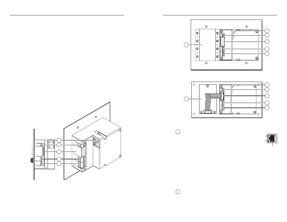
Figure 2-8 — MKP 3000 MAAP rear panel
3
1
2
4
5
7
Figure 2-9 — MKP 3000 L rear panel
1
LAN (Ethernet) port
— If desired, connect a
Category (CAT) 5e or higher (network) cable
between this connector and either the matrix
switcher to be controlled or to an Ethernet
local area network (LAN). See “Ethernet cable
termination,” later in this chapter, to properly
wire the RJ-45 connector for your application.
Ethernet connection indicators
— The Link and Activity LEDs
on the LAN port indicate the status of the Ethernet connection.
The green Link LED indicates that the MKP is properly
connected to an Ethernet LAN. This LED should light steadily.
The yellow Activity LED indicates transmission of data packets
on the RJ-45 connector. This LED should flicker as the MKP
communicates.
2
Power connector
— Connect the included external 12 VDC
power supply to this 2-pole direct insertion connector. See
“Power supply wiring,” on page 2-18, to wire the connector.
2-11
3.
Mechanical loading
— Mounting of the equipment in the
rack should be such that a hazardous condition is not
achieved due to uneven mechanical loading.
4.
Circuit overloading
— Consideration should be given to
the connection of the equipment to the supply circuit and
the effect that overloading of the circuits might have on
overcurrent protection and supply wiring. Appropriate
consideration of equipment nameplate ratings should be
used when addressing this concern.
5.
Reliable earthing (grounding)
— Reliable earthing of
rack-mounted equipment should be maintained.
Particular attention should be given to supply connections
other than direct connections to the branch circuit (for
example, use of power strips).
Rear Panel and Side Panel Connections
All connectors are on the rear or side of the MKP (figure 2-7, 2-8,
and 2-9). These connectors are inaccessible once the MKP is
installed.
GND
12 V
REMO
TE
KEYP
AD
POWER
.5A MAX
Tx
HOST
RS-232
SWITCH
RS-232
Rx
GND
Tx
Rx
GND
GND
12 V
REMO
TE
KEYP
AD
PO
WER
.5A MAX
Tx
HOST
RS-232
SWITCH
RS-232
Rx
GND
Tx
Rx
GND
3
1
2
4
5
Figure 2-7 — MKP 3000 rear and side panels
2-10
RJ-45
Port
Link
LED
Activity
LED