Rs-232 cable termination, Ethernet connection – Extron Electronics MKP 3000 Series User Manual
Page 16
MKP 3000 Series • Installation
MKP 3000 Series • Installation
Installation, cont’d
Wire the connectors as follows:
The total cable length between an MKP control panel
and a matrix switcher should not exceed 100 feet (30 m).
1
.
Choose a cable such as Extron’s Comm-Link cable. The
wire specifications for Comm-Link cable are in
appendix A, “Reference Information.” Colors may vary
from this example.
2
.
Trim approximately 1.5" (3.8 cm) of the cable jacket to
expose the four insulated wires and a bare drain wire
(silver-colored).
3
.
Cut off the foil shield and discard it.
4
.
Strip ¼" ( 0.6 cm) of insulation from three of the four wires.
5
.
Twist the strands of each wire, insert them into the direct
insertion connector, and tighten the captive screws.
Ethernet connection
An MKP control panel can be directly connected to any
Ethernet-enabled matrix switcher via the switcher’s Ethernet
port (figure 2-13) using a TP (network) cable that is wired as a
crossover cable (see “TP cable termination,” later in this chapter,
to properly wire the cable).
MKP 3000
Crossover
Cable
LAN Port
Matrix Switcher
I
N
P
U
T
S
CONTROL
O
U
T
P
U
T
S
I/O
1
2
3
4
5
6
7
8
9 10 11 12
13 14 15 16 17 18 19 20 21 22 23 24
1
2
3
4
5
6
7
8
9 10 11 12
13 14 15 16 17 18 19 20 21 22 23 24
MAV 2400 SERIES SWITCHER
I / O
SELECT
Extron
MKP 3000
Figure 2-14 — Direct MKP connection using the
LAN port
Any number of control panels can be connected as part of a
network to any Ethernet-enabled matrix switcher via the
switcher’s Ethernet port (figure 2-14). All TP cables in this
example are wired as patch (straight-through) cables.
2-15
2-14
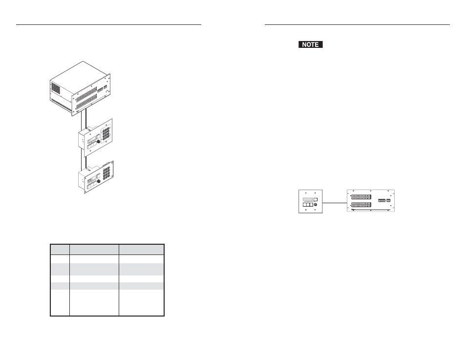
Multiple primary MKPs can also be daisy-chained together,
with the first MKP connected to the switcher’s RS-232 port and
the others connected to each other via their own RS-232 ports.
Figure 2-12 shows an example of this type of configuration.
MKP 3000
Primary/Pass-
through
MKP 3000 L
Primary/MKP 3000
Host
RS-232 Port
Switcher
RS-232 Port
Tx
Tx
Tx
Tx
Rx
Rx
Rx
Rx
Switcher
RS-232 Port
Matrix Switcher
I
N
P
U
T
S
CO
NT
RO
L
I/O
MA
V 3
20
0 S
ER
IE
S S
W
ITC
HER
I
N
P
U
T
S
O
U
T
P
U
T
S
16
15
14
13
12
11
10
9
8
7
6
5
4
3
2
1
16
15
14
13
12
11
10
9
8
7
6
5
4
3
2
1
32
31
30
29
28
27
26
25
24
23
22
21
20
19
18
17
32
31
30
29
28
27
26
25
24
23
22
21
20
19
18
17
PR
IM
AR
Y
RE
DU
ND
AN
T
PO
W
ER
S
UP
PL
Y
POW
ER
RES
ET
I/O
SE
LE
CT
BA
CK
CA
NC
EL
1
2
3
4
5
6
7
8
9
0
MK
P
10
Extr
on
MK
P 3
00
0 M
AA
P
Extr
on
PO
W
ER
RE
SE
T
I/O
SELECT
BA
CK
CA
NC
EL
1
2
3
4
5
6
7
8
9
0
VI
DE
O
GRE
EN
AU
DI
O
RE
D
TA
KE
OU
TP
UT
IN
PU
T
MK
P 3
00
0 L
Figure 2-12 — Daisy-chaining MKP 3000s
RS-232 cable termination
Each MKP control panel has two RS-232 ports that are
connected using 3.5 mm, 3-pole direct insertion connectors.
Figure 2-13 shows the pin assignments for these ports.
Pin Switcher RS-232
MKP RS-232
1
–
–
2
Tx
Rx
3
Rx
Tx
4
–
–
5
Gnd
Gnd
6
–
–
7
–
–
8
–
–
9
–
–
Figure 2-13 — RS-232 cross-connection table