Preliminar y – Extron Electronics MPX Plus 866 A Rev. B User Manual
Page 117
5-11
MPX Plus 866 A Media Presentation Matrix Switcher • Switcher Software
PRELIMINAR
Y
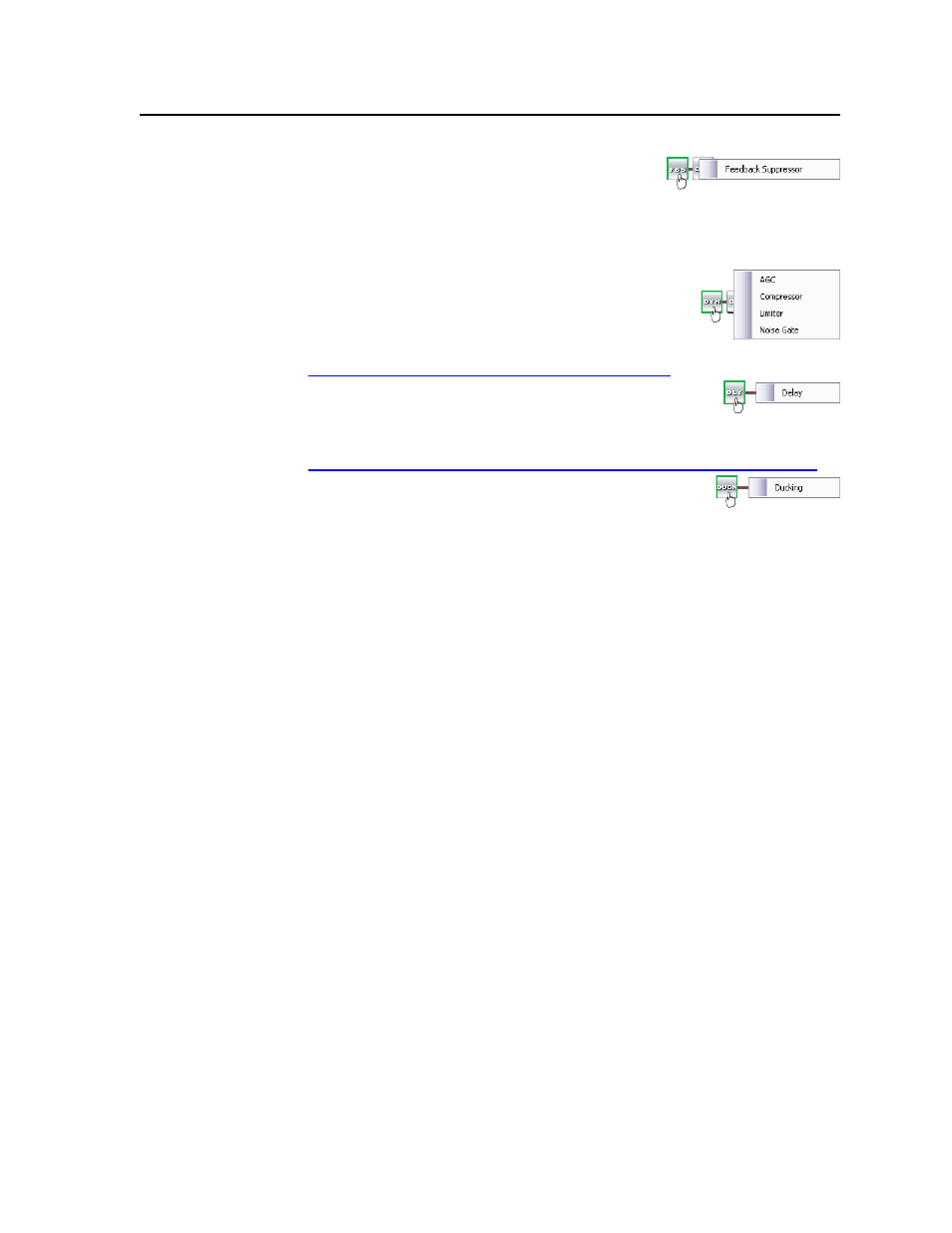
Feedback suppressor block —
The feedback
suppressor processor block, when inserted, detects
feedback on a live microphone channel, and uses a
set of fixed and dynamic filters to counteract the frequency peaks at the detected
feedback frequencies. You may possibly achieve an additional 3 dB to 9 dB of
mic gain where feedback would have otherwise prevented these levels.
Dynamics blocks (2) —
The two dynamics processor blocks,
when inserted, each provide one of four dynamic
processors. The available processors are identical to the
processors available on the input in the dynamics
processor block and described in “Program audio input
Delay block —
The delay processor block, when inserted,
provides a means to delay the audio signal if necessary to
sync it to video. The delay processor block is identical to the
delay processor available on the input and described in “Program audio input
Ducking block —
The ducking processor block, when
inserted, provides a means to duck, or lower the level of, one
or more microphones and/or the program material when
the processor detects a signal from another source. Ducking lasts for the
duration of the interrupting signal (plus hold and release time) and restores the
ducked mic’s original level once the other signal has ceased. Ducking is useful
when:
• Program material needs to be attenuated in order to more clearly hear the
narrator’s voice.
• One microphone, such as one used by a master of ceremonies, needs to have
priority over other mics and/or program material.
• A paging mic needs to attenuate all other signals.
There are three possible settings to insert a Mic/line input as a ducking source:
• Duck Outputs Only — Ducks only selected outputs.
• 1st Priority — Ducks other mics, plus selected outputs.
• 2nd Priority — Ducks selected outputs, and is ducked by another mic(s).
All four ducking processor blocks are controlled via a common dialog box that
opens when you select to configure any of the ducking blocks. When a Ducking
processor block is inserted, it is automatically set to the Duck Outputs Only in
the dialog box (whether the dialog box is opened or not). Conversely, when the
Ducking dialog window is open and any mic channel is set to Duck Outputs
Only
, the corresponding processor block in the main DSP Configurator window
becomes active.