GE Industrial Solutions Entellisys 5.0 Integrator's Guide User Manual
Page 95
95
4
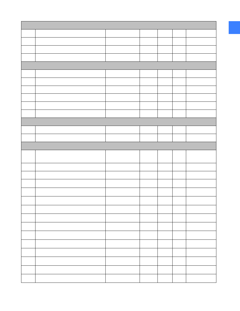
Contact Input Configuration (Read/Write Setting)(2 Modules)
7003
Board 1 I/O Direction High
0 to 4294967295
---
---
F737
0
7005
Board 1 I/O Direction Low
0 to 4294967295
---
---
F736
0
7007
Board 2 I/O Direction High
0 to 4294967295
---
---
F737
0
7009
Board 2 I/O Direction Low
0 to 4294967295
---
---
F736
0
Discrete IO Configuration (Read Only)
702A
Boards detected
0 to 8
---
1
F001
0
702B
Boards Used
0 to 8
---
1
F001
0
702C
Total I/O Points Available
0 to 65535
---
1
F001
0
702D
Contact Input Count
0 to 96
---
1
F001
0
702E
Contact Output Count
0 to 64
---
1
F001
0
702F
Boards Expected
0 to 2
---
1
F001
0
Expanded Digital I/O states (Read Only) (128 modules)
703F
Contact Input x State (128 items)
0 to 1
---
1
F108
0 (Off)
70BF
Contact Output x State (128 items)
0 to 1
---
1
F108
0 (Off)
Contact Inputs (Read/Write Setting) (128 modules)
713F
Contact Input x Name
---
---
---
F200
"Contact Input 1
"
7153
Contact Input x Events
0 to 1
---
1
F102
1 (Enabled)
7154
Contact Input x Debounce Time
0 to 4
us
1
F734
0
7155
Contact Input x Reserved (4 items)
7159
...Repeated for module number 2
7173
...Repeated for module number 3
718D
...Repeated for module number 4
71A7
...Repeated for module number 5
71C1
...Repeated for module number 6
71DB
...Repeated for module number 7
71F5
...Repeated for module number 8
720F
...Repeated for module number 9
7229
...Repeated for module number 10
7243
...Repeated for module number 11
725D
...Repeated for module number 12