1head - 1.6 interfacing to the alarm handler, 6 interfacing to the alarm handler – GE Industrial Solutions Entellisys 5.0 Integrator's Guide User Manual
Page 19
Interfacing to the Alarm Handler
19
1.6 Interfacing to the Alarm Handler
Source Vectors for Alarms on page 61
is a set of registers beginning at 0428 provides the
means to interface to each CUP’s Alarm Handler functionality. Each pair of 32-bit values
represent the current state (read only) and the acknowledge setting (read/write) for each alarm
type. Each value represents the states for all of the circuit breakers in the system as denoted in
Format Code F722, one bit for each. A 1 in the bit field position for a given circuit breaker in the
state register indicates that the alarm condition is currently active, while a 0 indicates the
condition is not currently active.
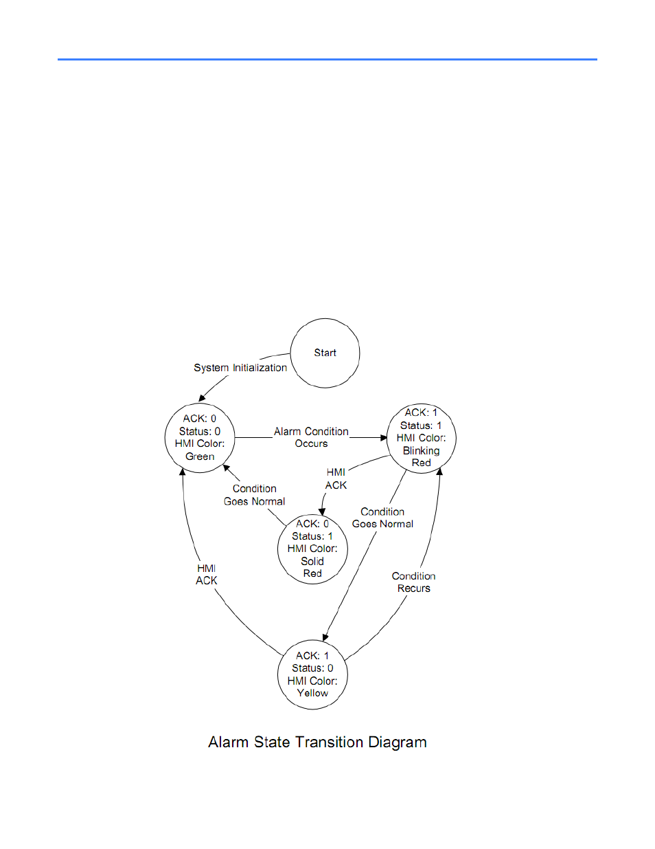
When a condition passes from inactive to active, the corresponding ACK bit in the next register
will be set to 1. At this point an external program may acknowledge the alarm by writing a 0 to
that bit location. It is important for the external program to first read the ACK register and mask
the new value such that the states represented by the other bits remain intact. The following
state table describes how the HMI interfaces with the CPU to update its indicators.
Figure 1-6 Alarm state transition diagram