Transmit side timing figure 13–5, Transmit side boundary timing figure 13–6 – Rainbow Electronics DS2154 User Manual
Page 53
DS2154
031197 53/69
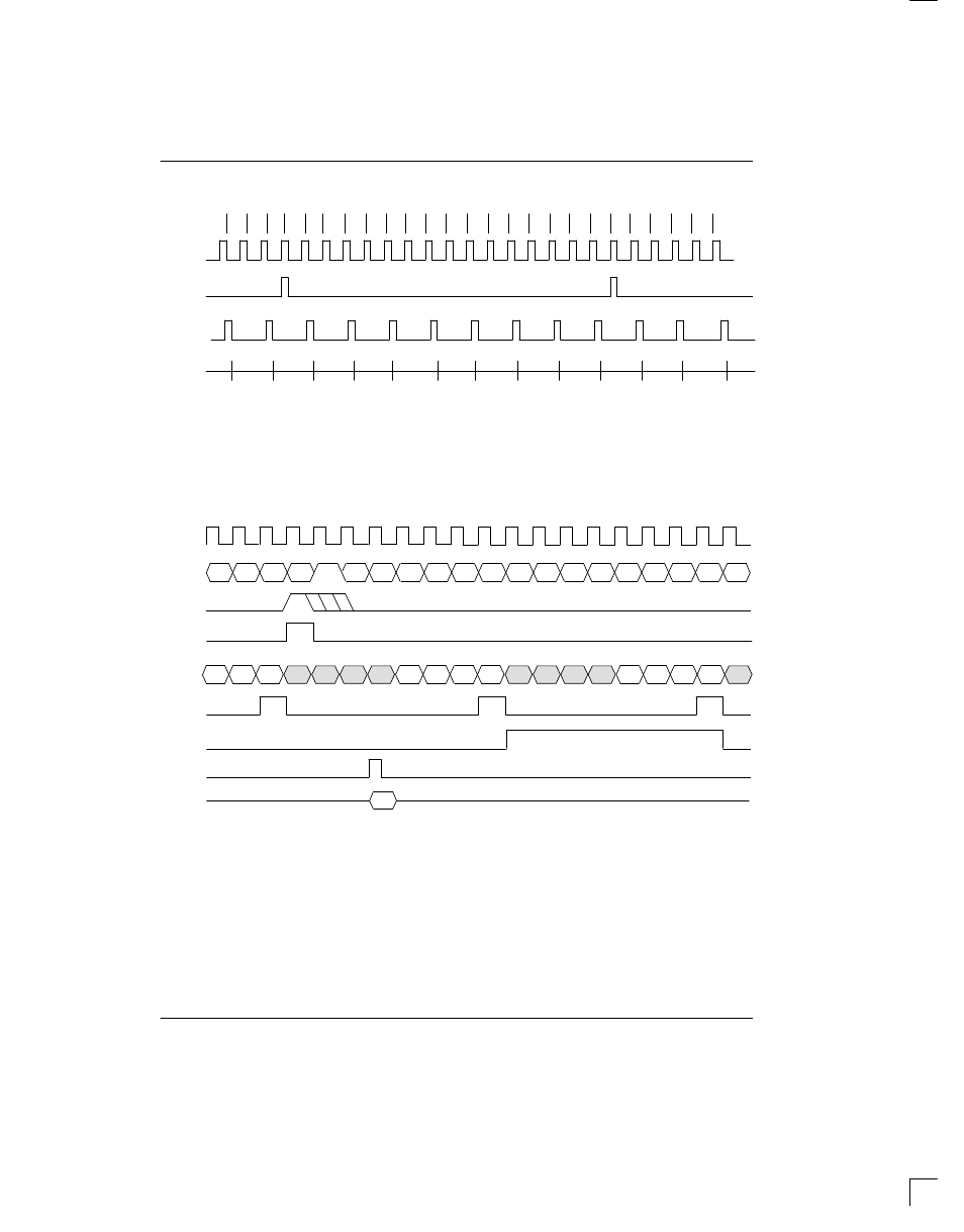
TRANSMIT SIDE TIMING Figure 13–5
15
16
1
2
3
4
5
6
7
8
9
10
11
12
13
14
15
FRAME#
16
1
2
3
4
5
6
14
TSYNC
1
/
TFSYNC
TSYNC
2
TLCLK
3
TLINK
3
NOTES:
1. TSYNC in the frame mode (TCR1.1=0).
2. TSYNC in the multiframe mode (TCR1.1=1).
3. TLINK is programmed to source only the Sa4 bit.
4. This diagram assumes both the CAS MF and the CRC4 begin with the align frame.
TRANSMIT SIDE BOUNDARY TIMING Figure 13–6
TCLK
TSER
TSYNC
1
/
TFSYNC
TSYNC
2
TCHCLK
CHANNEL 2
CHANNEL 1
TCHBLK
3
TLCLK
4
TLINK
4
Don’t Care
LSB
Si
1
A
Sa4
Sa5
Sa6
Sa7
Sa8
MSB
MSB
LSB
Don’t Care
TSIG
B
CHANNEL 2
CHANNEL 1
CHANNEL 32
C
D
A
B
C
D
NOTES:
1. TSYNC is in the input mode (TCR1.0=0).
2. TSYNC is in the output mode (TCR1.0=1).
3. TCHBLK is programmed to block Channel 2.
4. TLINK is programmed to source the Sa4 bits.
5. The signaling data at TSIG during Channel 1 is normally overwritten in the transmit formatter with the CAS
multiframe alignment nibble (0000).
6. Shown is a non–align frame boundary.