Rainbow Electronics DS2154 User Manual
Page 37
DS2154
031197 37/69
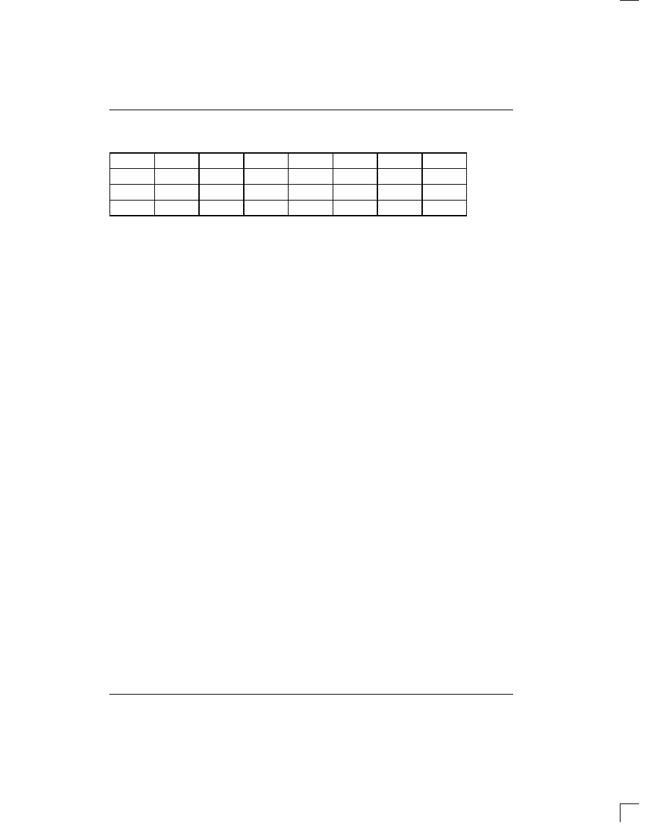
TCBR1/TCBR2/TCBR3/TCBR4: DEFINITION WHEN CCR3.6=1
(MSB)
(LSB)
CH20
CH4
CH19
CH3
CH18
CH2
CH17*
CH1*
CH24
CH8
CH23
CH7
CH22
CH6
CH21
CH5
CH28
CH12
CH27
CH11
CH26
CH10
CH25
CH9
CH32
CH16
CH31
CH15
CH30
CH14
CH29
CH13
*=CH1 and CH17 should be set to one to allow the internal TS1 register to create the CAS Multiframe Alignment Word
and Spare/Remote Alarm bits.
The user can also take advantage of this functionality to
intermix signaling data from the TSIG pin and from the
internal Transmit Signaling Registers (TS1 to TS16). As
an example, assume that the user wishes to source all
the signaling data except for voice channels 5 and 10
from the TSIG pin. In this application, the following bits
and registers would be programmed as follows:
CONTROL BITS
REGISTER VALUES
TSRE=1 (CCR3.2)
TS1=0Bh (MF alignment word, remote alarm etc.)
TCBFS=1 (CCR3.6)
TCBR1=03h (source timeslot 16, frame 1 data)
T16S=1 (TCR1.5)
TCBR2=01h (source voice Channel 5 signaling data from TS6)
TCBR3=04h (source voice Channel 10 signaling data from TS11)
TCBR4=00h
8.0
PER–CHANNEL CODE GENERATION
The DS2154 can replace data on a channel–by–chan-
nel basis in both the transmit and receive directions.
The transmit direction is from the backplane to the E1
line and is covered in Section 8.1. The receive direction
is from the E1 line to the backplane and is covered in
Section 8.2.
8.1
TRANSMIT SIDE CODE GENERATION
In the transmit direction there are two methods by which
channel data from the backplane can be overwritten
with data generated by the DS2154. The first method
which is covered in Section 8.1.1 was a feature con-
tained in the original DS2153 while the second method
which is covered in Section 8.1.2 is a new feature of the
DS2154.
8.1.1
Simple Idle Code Insertion and
Per–Channel Loopback
The first method involves using the Transmit Idle Regis-
ters (TIR1/2/3/4) to determine which of the 32 E1 chan-
nels should be overwritten with the code placed in the
Transmit Idle Definition Register (TIDR). This method
allows the same 8–bit code to be placed into any of the
32 E1 channels. If this method is used, then the CCR3.5
control bit must be set to zero.
The Transmit Idle Registers (TIRs) have an alternate
function that allow them to define a Per–Channel Loop-
Back (PCLB). If the CCR3.5 control bit is set to one,
then the TIRs will determine which channels (if any)
from the backplane should be replaced with the data
from the receive side or in other words, off of the E1 line.
See Figure 1–1. If this mode is enabled, then transmit
and receive clocks and frame syncs must be synchro-
nized. One method to accomplish this would be to tie
RCLK to TCLK and RFSYNC to TSYNC. There are no
restrictions on which channels can be loopback or on
how many channels can be looped back.
TCBR1(22)
TCBR2(23)
TCBR3(24)
TCBR4(25)