Rainbow Electronics DS2154 User Manual
Page 52
DS2154
031197 52/69
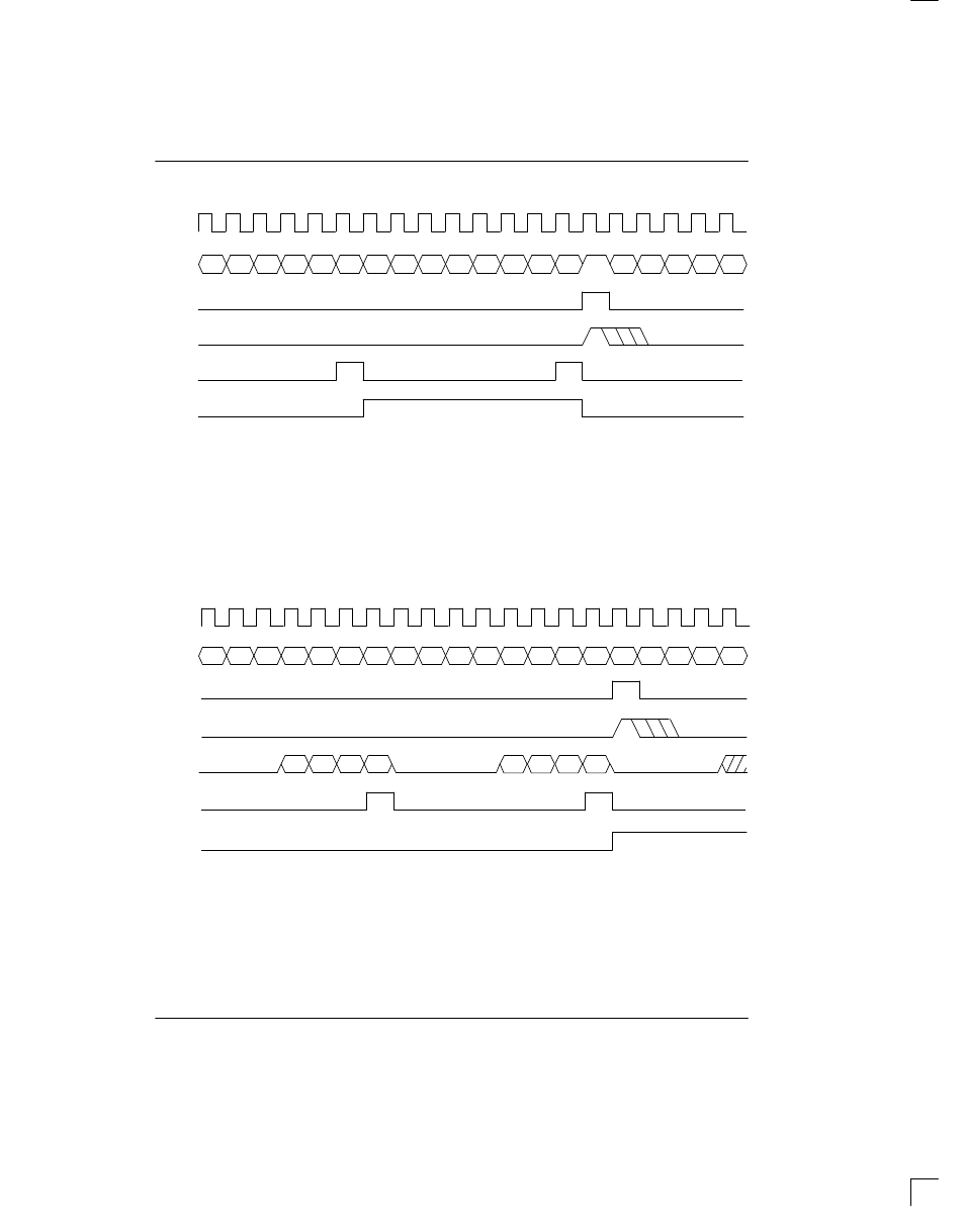
RECEIVE SIDE 1.544 MHz BOUNDARY TIMING (WITH ELASTIC STORE ENABLED) Figure 13–3
RSYSCLK
RSER
1
RSYNC
2
/
RMSYNC
RSYNC
3
RCHCLK
RCHBLK
4
CHANNEL 24/32
CHANNEL 1/2
CHANNEL 23/31
LSB
MSB
LSB
MSB
F
NOTES:
1. Data from the E1 Channels 1, 5, 9, 13, 17, 21, 25, and 29 is dropped (Channel 2 from the E1 link is mapped
to Channel 1 of the T1 link, etc.) and the F–bit position is added (forced to one).
2. RSYNC is in the output mode (RCR1.5=0).
3. RSYNC is in the input mode (RCR1.5=1).
4. RCHBLK is programmed to block Channel 24.
RECEIVE SIDE 2.048 MHz BOUNDARY TIMING (WITH ELASTIC STORE ENABLED) Figure 13–4
RSYSCLK
RSER
RSYNC
1
/
RMSYNC
RSYNC
2
RCHCLK
RCHBLK
3
CHANNEL 32
CHANNEL 1
CHANNEL 31
LSB
MSB
LSB
MSB
RSIG
A
B
C
D
CHANNEL 31
CHANNEL 1
CHANNEL 32
NOTE 4
A
B
C
D
NOTES:
1. RSYNC is in the output mode (RCR1.5=0).
2. RSYNC is in the input mode (RCR1.5=1).
3. RCHBLK is programmed to block Channel 1.
4. RSIG normally contains the CAS multiframe alignment nibble (0000) in Channel 1.