Rainbow Electronics DS2154 User Manual
Page 41
DS2154
031197 41/69
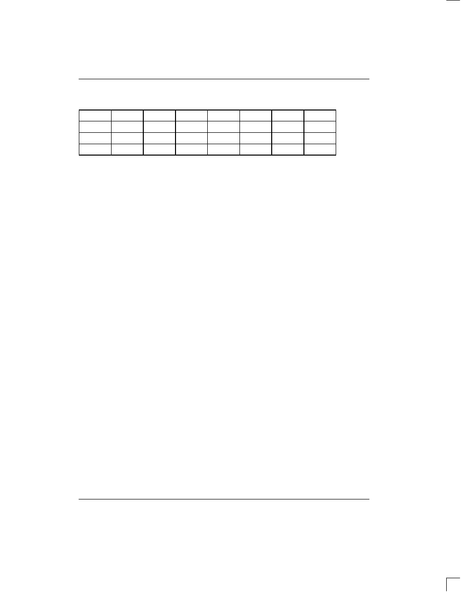
TCBR1/TCBR2/TCBR3/TCBR4: DEFINITION WHEN CCR3.6=1
(MSB)
(LSB)
CH20
CH4
CH19
CH3
CH18
CH2
CH17*
CH1*
CH24
CH8
CH23
CH7
CH22
CH6
CH21
CH5
CH28
CH12
CH27
CH11
CH26
CH10
CH25
CH9
CH32
CH16
CH31
CH15
CH30
CH14
CH29
CH13
*=CH1 and CH17 should be set to one to allow the internal TS1 register to create the CAS Multiframe Alignment Word
and Spare/Remote Alarm bits.
10.0 ELASTIC STORES OPERATION
The DS2154 contains dual two–frame (512 bits) elastic
stores, one for the receive direction, and one for the
transmit direction. These elastic stores have two main
purposes. First, they can be used to rate convert the E1
data stream to 1.544 Mbps (or a multiple of 1.544 Mbps)
which is the T1 rate. Secondly, they can be used to
absorb the differences in frequency and phase between
the E1 data stream and an asynchronous (i.e., not fre-
quency locked) backplane clock which can be
1.544 MHz or 2.048 MHz. The backplane clock can
burst at rates up to 8.192 MHz. Both elastic stores con-
tain full controlled slip capability which is necessary for
this second purpose. The elastic stores can be forced to
a known depth via the Elastic Store Reset bit (CCR3.4).
Toggling the CCR3.4 bit forces the read and write point-
ers into opposite frames. Both elastic stores within the
DS2154 are fully independent and no restrictions apply
to the sourcing of the various clocks that are applied to
them. The transmit side elastic store can be enabled
whether the receive elastic store is enabled or disabled
and vice versa. Also, each elastic store can interface to
either a 1.544 MHz or 2.048 MHz backplane without
regard to the backplane rate the other elastic store is in-
terfacing.
10.1 RECEIVE SIDE
If the receive side elastic store is enabled (RCR2.1=1),
then the user must provide either a 1.544 MHz (RCR2.2
=0) or 2.048 MHz (RCR2.2=1) clock at the RSYSCLK
pin. The the user has the option of either providing a
frame/multiframe sync at the RSYNC pin (RCR1.5=1)
or having the RSYNC pin provide a pulse on frame/mul-
tiframe boundaries (RCR1.5=0). If the user wishes to
obtain pulses at the frame boundary, then RCR1.6 must
be set to zero and if the user wishes to have pulses
occur at the multiframe boundary, then RCR1.6 must be
set to one. The DS2154 will always indicate frame
boundaries via the RFSYNC output whether the elastic
store is enabled or not. If the elastic store is enabled,
then either CAS (RCR1.7=0) or CRC4 (RCR1.7=1) mul-
tiframe boundaries will be indicated via the RMSYNC
output. If the user selects to apply a 1.544 MHz clock to
the RSYSCLK pin, then every fourth channel of the
received E1 data will be deleted and a F–bit position
(which will be forced to one) will be inserted. Hence
Channels 1, 5, 9, 13, 17, 21, 25, and 29 (timeslots 0, 4, 8,
12, 16, 20, 24, and 28) will be deleted from the received
E1 data stream. Also, in 1.544 MHz applications, the
RCHBLK output will not be active in Channels 25
through 32 (or in other words, RCBR4 is not active).
See Section 13 for timing details. If the 512–bit elastic
buffer either fills or empties, a controlled slip will occur. If
the buffer empties, then a full frame of data (256–bits)
will be repeated at RSER and the SR1.4 and RIR.3 bits
will be set to a one. If the buffer fills, then a full frame of
data will be deleted and the SR1.4 and RIR.4 bits will be
set to a one.
10.2 TRANSMIT SIDE
The operation of the transmit elastic store is very similar
to the receive side. The transmit side elastic store is
enabled via CCR3.7. A 1.544 MHz (CCR3.1=0) or
2.048 MHz (CCR3.1=1) clock can be applied to the
TSYSCLK input. The TSYSCLK can be a bursty clock
with rates up to 8.192 MHz. If the user selects to apply a
1.544 MHz clock to the TSYSCLK pin, then the data
sampled at TSER will be ignored every fourth channel.
Hence Channels 1, 5, 9, 13, 17, 21, 25, and 29 (timeslots
0, 4, 8, 12, 16, 20, 24, and 28) will be ignored. The user
must supply a 8 KHz frame sync pulse to the TSSYNC
input. See Section 13 for timing details. Controlled slips
in the transmit elastic store are reported in the SR2.0 bit
and the direction of the slip is reported in the RIR.6 and
RIR.7 bits.
TCBR1(22)
TCBR2(23)
TCBR3(24)
TCBR4(25)