Rainbow Electronics DS2154 User Manual
Page 11
DS2154
031197 11/69
Receive Analog Positive Supply [RVDD]. 5.0 volts
±
5%. Should be tied to the DVDD and TVDD pins.
Transmit Analog Positive Supply [TVDD]. 5.0 volts
±
5%. Should be tied to the RVDD and DVDD pins.
Digital Signal Ground [DVSS]. 0.0 volts. Should be
tied to the RVSS and TVSS pins.
Receive Analog Signal Ground [RVSS]. 0.0 volts.
Should be tied to the DVSS and TVSS pins.
Transmit Analog Ground [TVSS]. 0.0 volts. Should
be tied to the RVSS and DVSS pins.
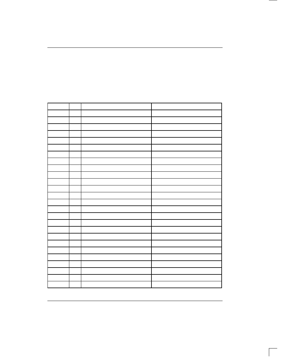
DS2154 REGISTER MAP Table 1–3
ADDRESS
R/W
REGISTER NAME
REGISTER ABBREVIATION
00
R
BPV or Code Violation Count 1.
VCR1
01
R
BPV or Code Violation Count 2.
VCR2
02
R
CRC4 Error Count 1 / FAS Error Count 1.
CRCCR1
03
R
CRC4 Error Count 2.
CRCCR2
04
R
E–Bit Count 1 / FAS Error Count 2.
EBCR1
05
R
E–Bit Count 2.
EBCR2
06
R/W
Status 1.
SR1
07
R/W
Status 2.
SR2
08
R/W
Receive Information.
RIR
09
–
not present.
–
0A
–
not present.
–
0B
–
not present.
–
0C
–
not present.
–
0D
–
not present.
–
0E
–
not present.
–
0F
R
Device ID Register.
IDR
10
R/W
Receive Control 1.
RCR1
11
R/W
Receive Control 2.
RCR2
12
R/W
Transmit Control 1.
TCR1
13
R/W
Transmit Control 2.
TCR2
14
R/W
Common Control 1.
CCR1
15
R/W
Test 1.
TEST1 (set to 00h)
16
R/W
Interrupt Mask 1.
IMR1
17
R/W
Interrupt Mask 2.
IMR2
18
R/W
Line Interface Control.
LICR
19
R/W
Test 2.
TEST2 (set to 00h)