Rainbow Electronics DS2154 User Manual
Page 51
DS2154
031197 51/69
13.0 TIMING DIAGRAMS/SYNC FLOWCHART/TRANSMIT DATA FLOW DIAGRAM
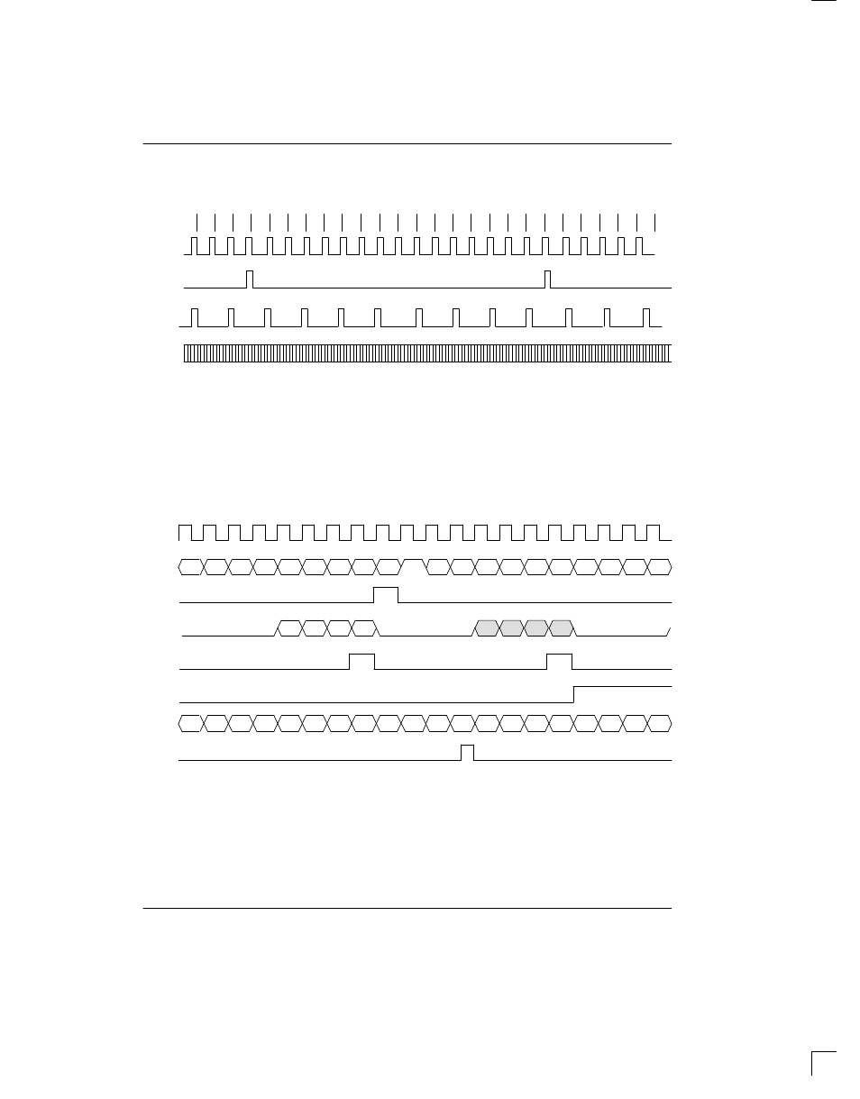
RECEIVE SIDE TIMING Figure 13–1
15
16
1
2
3
4
5
6
7
8
9
10
11
12
13
14
15
FRAME#
16
1
2
3
4
5
6
14
RSYNC
1
/
RFSYNC
RSYNC
2
RLCLK
3
RLINK
4
NOTES:
1. RSYNC in the frame mode (RCR1.6=0).
2. RSYNC in the multiframe mode (RCR1.6=1).
3. RLCLK is programmed to pulse high during the Sa4 bit position.
4. RLINK will always output all five Sa bits as well as the rest of the receive data stream.
5. This diagram assumes the CAS MF begins with the FAS word.
RECEIVE SIDE BOUNDARY TIMING (WITH ELASTIC STORE DISABLED) Figure 13–2
RCLK
RSYNC/
RFSYNC
RCHCLK
RCHBLK
1
RSIG
CHANNEL 32
MSB
CHANNEL 2
LSB
Si
1
A
MSB
Sa4
Sa5
Sa6
Sa7
Sa8
RSER/
RDATA
CHANNEL 1
A
B
C
D
CHANNEL 32
CHANNEL 2
CHANNEL 1
NOTE 4
MSB
Sa4
Sa5
Sa6
Sa7
Sa8
RLINK
RLCLK
2
NOTES:
1. RCHBLK is programmed to block Channel 2.
2. RLCLK is programmed to pulse high during the Sa4 bits position.
3. Shown is a non–align frame boundary.
4. RSIG normally contains the CAS multiframe alignment nibble (0000) in Channel 1.