Rainbow Electronics DS2154 User Manual
Page 32
DS2154
031197 32/69
TCM3
CCR4.3
Transmit Channel Monitor Bit 3.
TCM2
CCR4.2
Transmit Channel Monitor Bit 2.
TCM1
CCR4.1
Transmit Channel Monitor Bit 1.
TCM0
CCR4.0
Transmit Channel Monitor Bit 0. LSB of the channel decode that deter-
mines which transmit DS0 channel data will appear in the TDS0M register.
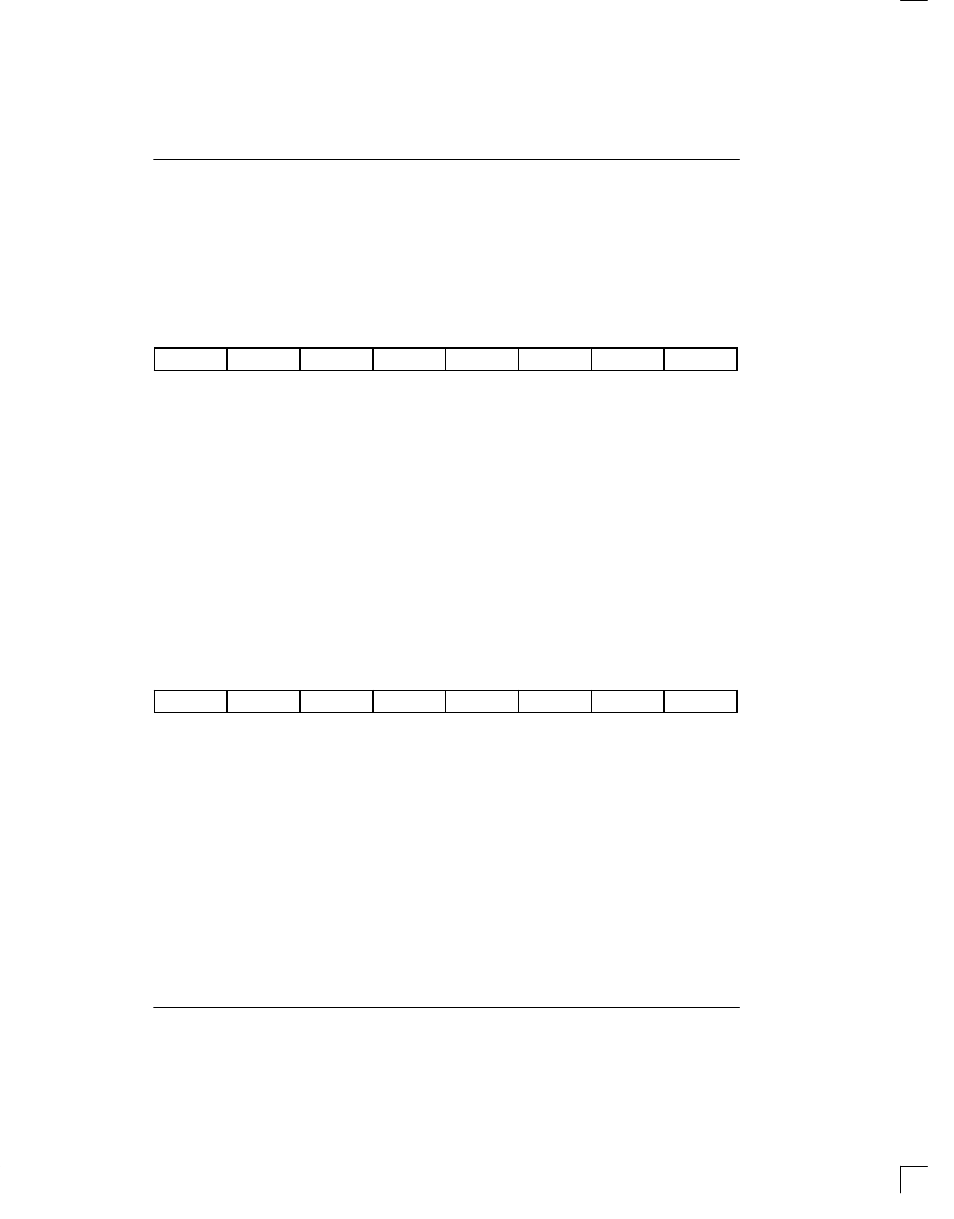
TDS0M: TRANSMIT DS0 MONITOR REGISTER (Address=A9 Hex)
(MSB)
(LSB)
B1
B2
B3
B4
B5
B6
B7
B8
SYMBOL
POSITION
NAME AND DESCRIPTION
B1
TDS0M.7
Transmit DS0 Channel Bit 8. MSB of the DS0 channel (first bit to be trans-
mitted).
B2
TDS0M.6
Transmit DS0 Channel Bit 7.
B3
TDS0M.5
Transmit DS0 Channel Bit 6.
B4
TDS0M.4
Transmit DS0 Channel Bit 5.
B5
TDS0M.3
Transmit DS0 Channel Bit 4.
B6
TDS0M.2
Transmit DS0 Channel Bit 3.
B7
TDS0M.1
Transmit DS0 Channel Bit 2.
B8
TDS0M.0
Transmit DS0 Channel Bit 1. LSB of the DS0 channel (last bit to be trans-
mitted).
CCR5: COMMON CONTROL REGISTER 5 (Address=AA Hex)
[repeated here from section 3 for convenience]
(MSB)
(LSB)
LIRST
–
–
RCM4
RCM3
RCM2
RCM1
RCM0
SYMBOL
POSITION
NAME AND DESCRIPTION
LIRST
CCR5.7
Line Interface Reset. See Section 3 for details.
–
CCR5.6
Not Assigned. Should be set to zero when written.
–
CCR5.5
Not Assigned. Should be set to zero when written.
RCM4
CCR5.4
Receive Channel Monitor Bit 4. MSB of a channel decode that deter-
mines which receive DS0 channel data will appear in the RDS0M register.
RCM3
CCR5.3
Receive Channel Monitor Bit 3.
RCM2
CCR5.2
Receive Channel Monitor Bit 2.
RCM1
CCR5.1
Receive Channel Monitor Bit 1.
RCM0
CCR5.0
Receive Channel Monitor Bit 0. LSB of the channel decode that deter-
mines which receive DS0 channel data will appear in the RDS0M register.