Tc channel mode register: waveform mode – Rainbow Electronics AT75C310 User Manual
Page 91
AT75C310
91
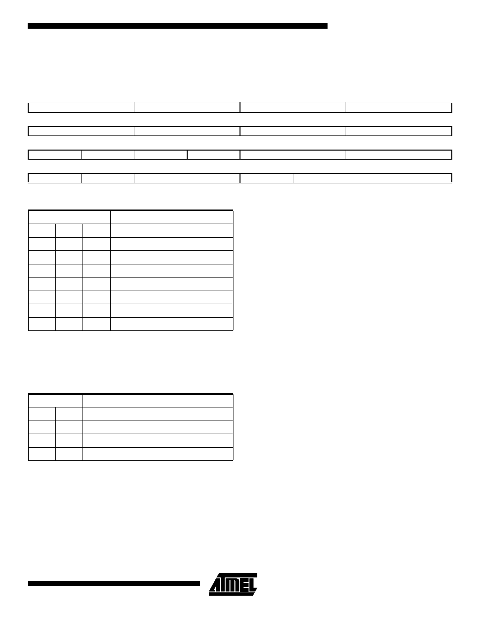
TC Channel Mode Register: Waveform Mode
Register Name:
TC_CMR
Access Type:
Read/write
•
TCCLKS: Clock Selection
•
CLKI: Clock Invert
0 = Counter is incremented on rising edge of the clock.
1 = Counter is incremented on falling edge of the clock.
•
BURST: Burst Signal Selection
•
CPCSTOP: Counter Clock Stopped with RC Compare
0 = Counter clock is not stopped when counter reaches RC.
1 = Counter clock is stopped when counter reaches RC.
•
CPCDIS: Counter Clock Disable with RC Compare
0 = Counter clock is not disabled when counter reaches RC.
1 = Counter clock is disabled when counter reaches RC.
31
30
29
28
27
26
25
24
BSWTRG
BEEVT
BCPC
BCPB
23
22
21
20
19
18
17
16
ASWTRG
AEEVT
ACPC
ACPA
15
14
13
12
11
10
9
8
WAVE=1
CPCTRG
–
ENETRG
EEVT
EEVTEDG
7
6
5
4
3
2
1
0
CPCDIS
CPCSTOP
BURST
CLKI
TCCLKS
TCCLKS
Clock Selected
0
0
0
ACLK/2
0
0
1
ACLK/8
0
1
0
ACLK/32
0
1
1
ACLK/128
1
0
0
ACLK/1024
1
0
1
XC0
1
1
0
XC1
1
1
1
XC2
BURST
0
0
The clock is not gated by an external signal
0
1
XC0 is ANDed with the selected clock
1
0
XC1 is ANDed with the selected clock
1
1
XC2 is ANDed with the selected clock