Rainbow Electronics AT75C310 User Manual
Page 13
AT75C310
13
•
LP: Low Power Mode
When high, the ARM is clocked at the low-power frequency. The DMC clock is disabled so the DRAM refresh is also
disabled. This field can only be set to high. Writing a zero to this field has no effect. Low-power mode can only be
exited by a reset. See the section “Clocking” on page 10 for more details.
•
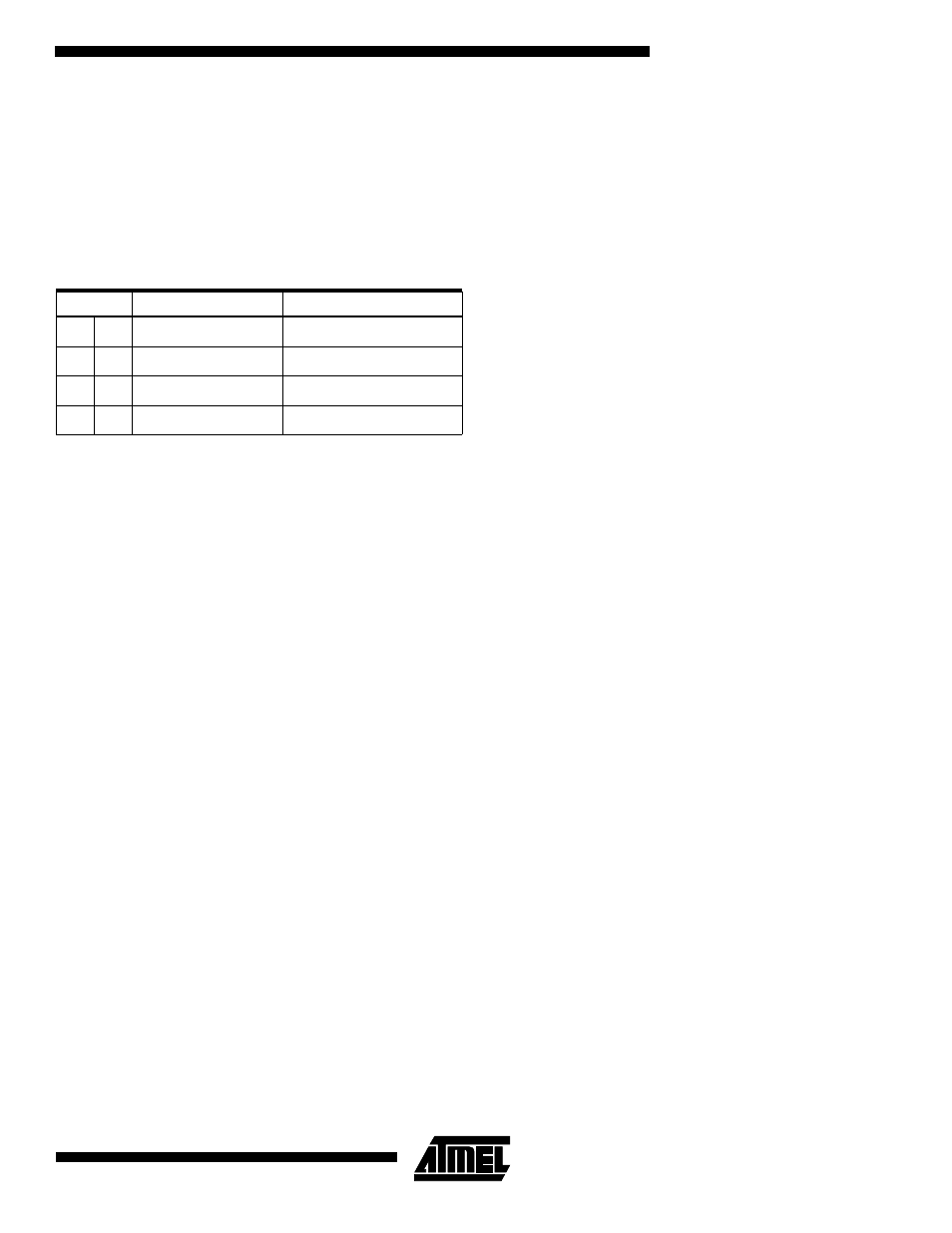
LPCS: Low Power Clock Select
This field is used to select a slower clock frequency for the ARM system clock. This field is sampled when the LP flag is
changed from low to high. When the LP flag is low, this field is ignored. Once the LP flag has been set high, further
changes to this field have no effect. See the section “Clocking” on page 10 for more details.
•
DBA: Oak A Debug Mode
This flag resets low. This bit should be set to enter Oak A debug mode (test-specific pins are multiplexed out on func-
tional pins).
•
DBB: Oak B Debug Mode
This flag resets low. This bit should be set to enter Oak B debug mode (test-specific pins are multiplexed out on func-
tional pins).
•
CRA: Codec A Reset
This flag resets to active low so that the Codec A is held in reset. The Codec A is released from reset by asserting this
flag high.
•
CRB: Codec B Reset
This flag resets to active low so that the Codec A is held in reset. The Codec A is released from reset by asserting this
flag high.
•
SW1: Software Reset 1
Writing a one to this bit forces the AT75C310 into reset with RM set to zero.
•
SW2: Software Reset 2
Writing a one to this bit forces the AT75C310 into reset with RM set to one.
LPCS
Divisor
ACLK Frequency
0
0
1
8 MHz
0
1
32
500 kHz
1
0
128
125 kHz
1
1
1024
16 kHz