Time-out, Transmitter, Time-guard – Rainbow Electronics AT75C310 User Manual
Page 57: Multi-drop mode
AT75C310
57
Time-out
This function allows an idle condition on the RXD line to be
detected. The maximum delay for which the USART should
wait for a new character to arrive while the RXD line is inac-
tive (high level) is programmed in US_RTOR (Receiver
Time-out). When this register is set to 0, no time-out is
detected. Otherwise, the receiver waits for a first character
and then initializes a counter which is decremented at each
bit period and reloaded at each byte reception. When the
counter reaches 0, the TIMEOUT bit in US_CSR is set. The
user can restart the wait for a first character with the
STTTO (Start Time-out) bit in US_CR.
Calculation of time-out duration:
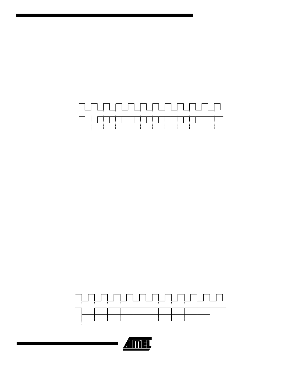
Figure 13. Synchronous Mode: Character Reception
Transmitter
The transmitter has the same behavior in both synchro-
nous and asynchronous operating modes. Start bit, data
bits, parity bit and stop bits are serially shifted, lowest sig-
nificant bit first, on the falling edge of the serial clock. See
the example in Figure 14.
The number of data bits is selected in the CHRL field in
US_MR.
The parity bit is set according to the PAR field in US_MR.
The number of stop bits is selected in the NBSTOP field in
US_MR.
When a character is written to US_THR (Transmit Holding),
it is transferred to the Shift Register as soon as it is empty.
When the transfer occurs, the TXRDY bit in US_CSR is set
until a new character is written to US_THR. If the Transmit
Shift Register and US_THR are both empty, the TXEMPTY
bit in US_CSR is set.
Time-guard
The time-guard function allows the transmitter to insert an
idle state on the TXD line between two characters. The
duration of the idle state is programmed in US_TTGR
(Transmitter Time-guard). When this register is set to zero,
no time-guard is generated. Otherwise, the transmitter
holds a high level on TXD after each transmitted byte dur-
ing the number of bit periods programmed in US_TTGR.
Multi-drop Mode
When the field PAR in US_MR equals 11X (binary value),
the USART is configured to run in multi-drop mode. In this
case, the parity error bit PARE in US_CSR is set when data
is detected with a parity bit set to identify an address byte.
PARE is cleared with the Reset Status Bits Command
(RSTSTA) in US_CR. If the parity bit is detected low identi-
fying a data byte, PARE is not set.
The transmitter sends an address byte (parity bit set) when
a Send Address Command (SENDA) is written to US_CR.
In this case, the next byte written to US_THR will be trans-
mitted as an address. After this, any byte transmitted will
have the parity bit cleared.
Figure 14. Synchronous and Asynchronous Modes: Character Transmission
Duration
Value
4
×
Bit Period
×
=
D0
D1
D2
D3
D4
D5
D6
D7
RXD
True Start Detection
Sampling
Parity Bit
Stop Bit
Example: 8-bit, parity enabled 1 stop
SCK
Idle state duration
between two characters
=
Time-guard
value
x
Bit
period
D0
D1
D2
D3
D4
D5
D6
D7
TXD
Start
Bit
Parity
Bit
Stop
Bit
Example: 8-bit, parity enabled 1 stop
Baud Rate
Clock