Spi: serial peripheral interface – Rainbow Electronics AT75C310 User Manual
Page 101
AT75C310
101
SPI: Serial Peripheral Interface
The serial peripheral interface provides communication
with external devices in master or slave mode. It also
allows communication with external processors or serial
Flash.
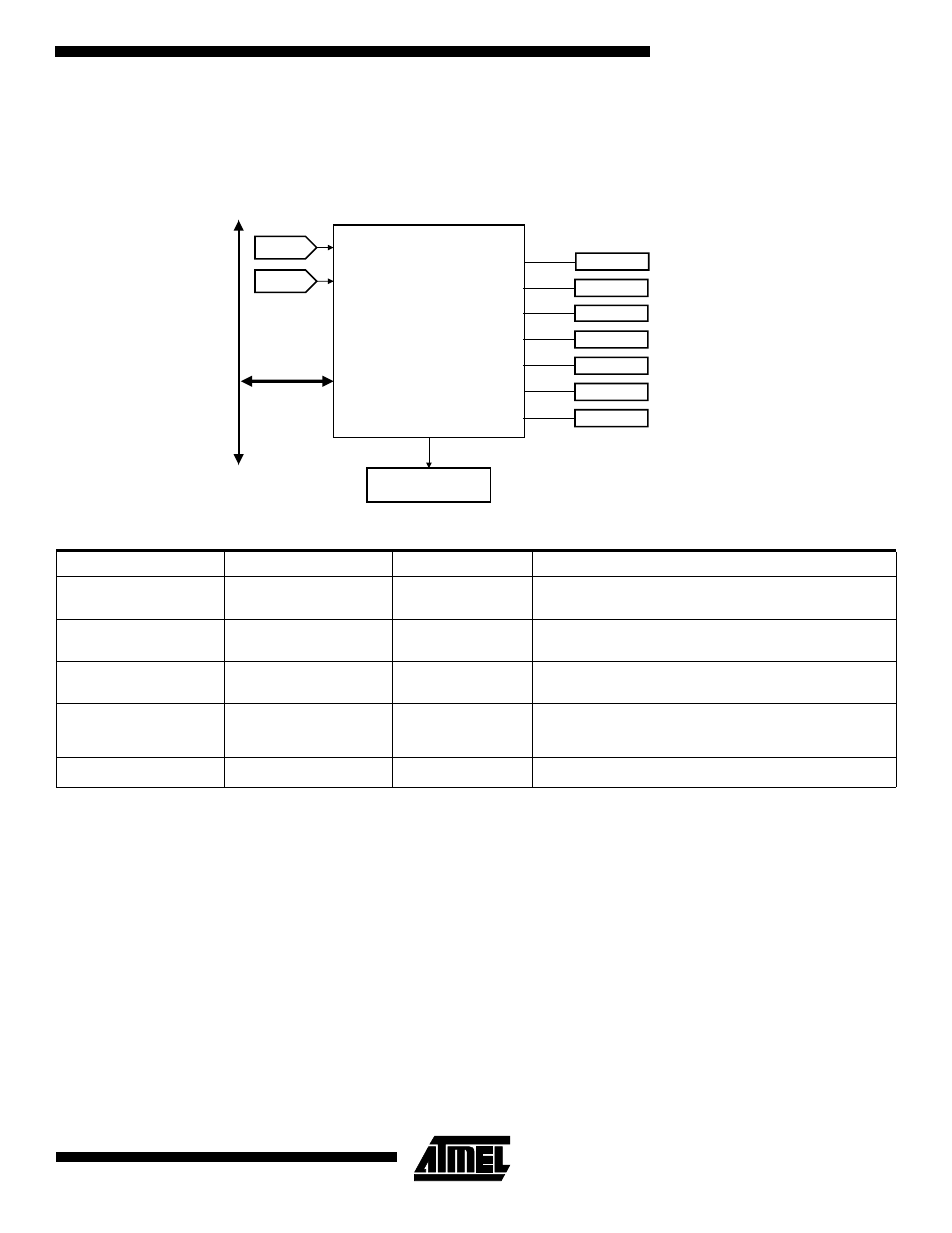
Figure 21. SPI Block Diagram
Note:
1. After a hardware reset, the SPI pins NPCS[3:1] are not enabled by default and must be programmed via the PIO A controller.
Table 20. SPI Interface Pins
Pin Name
Description
Mode
Function
MISO
Master In/Slave Out
Master
Slave
Serial data input to SPI
Serial data output from SPI
MOSI
Master Out/Slave In
Master
Slave
Serial data output from SPI
Serial data input to SPI
SPCK
Serial Clock
Master
Slave
Clock output from SPI
Clock input to SPI
NPCSS
Peripheral Chip Select/
Slave Select
Master
Master
Slave
Output: Selects peripheral
Input: Low causes mode fault
Input: Chip select for SPI
NPCS[3:1]
Peripheral Chip Selects
Master
Extra selects
Serial Peripheral Interface
APB
ACLK
ACLK/32
MISO
MISO
MOSI
MOSI
SPCK
SPCK
NPCSS
NPCSS
NPCS1
NPCS1
INT
Advanced
Interrupt Controller
NPCS2
NPCS3
NPCS2
NPCS3