Pin description, Baud rate generator – Rainbow Electronics AT75C310 User Manual
Page 54
AT75C310
54
Pin Description
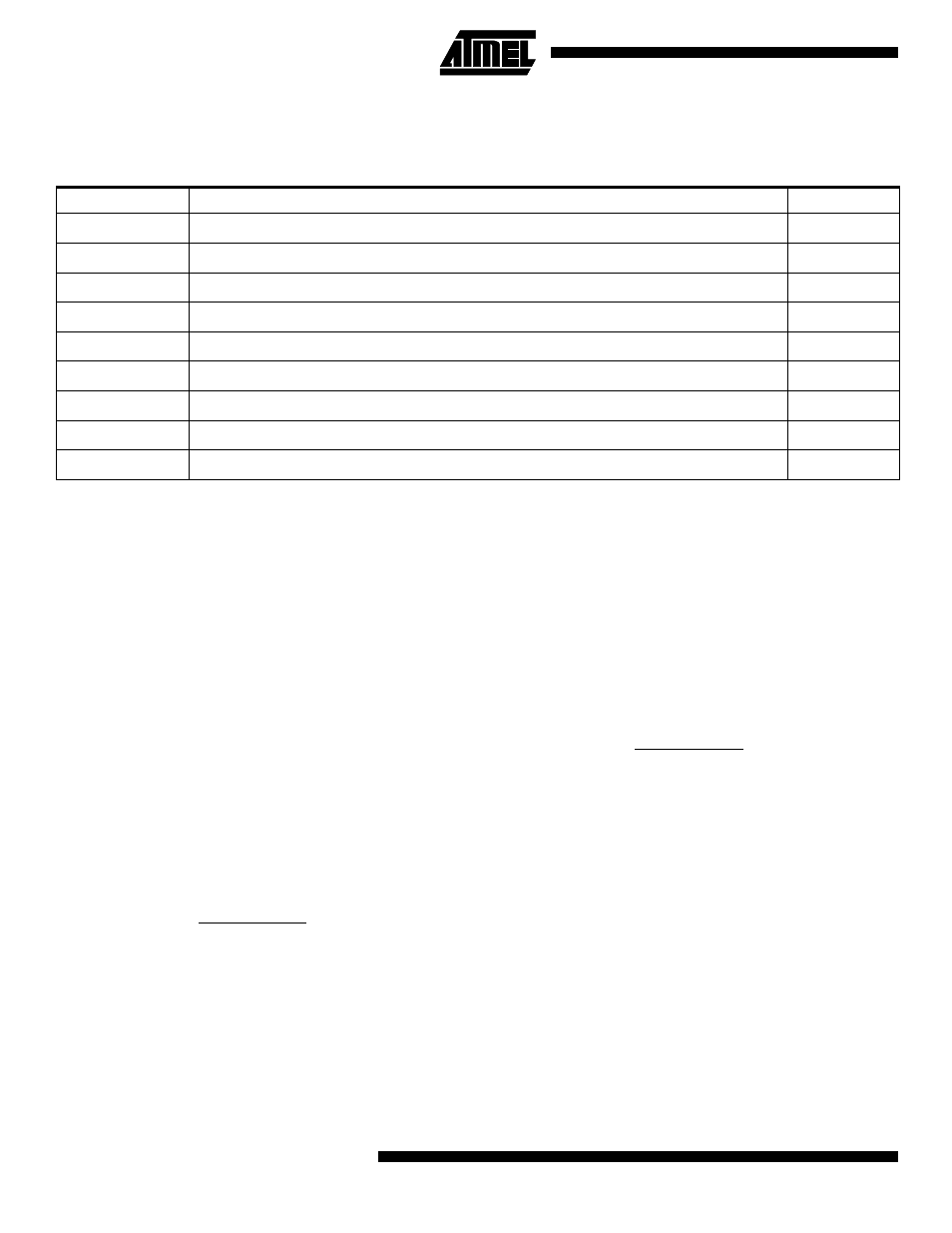
Each USART channel has the following external signals:
Note:
After a hardware reset, the USART pins are deselected by default (see “PIO: Parallel I/O Controller” on page 40). The user must
configure the PIO Controller before enabling the transmitter or receiver.
If the user selects one of the internal clocks, SCK can be configured as a PIO.
In addition, USART A signals NDSRA, NDCDA and NRIA are only available via the PIO A pins for the 160-lead PQFP package
option.
Baud Rate Generator
The baud rate generator provides the bit period clock (the
baud rate clock) to both the receiver and the transmitter.
The baud rate generator can select between external and
internal clock sources. The external clock source is SCK.
The internal clock sources can be either the master clock
ACLK or the master clock divided by 8 (ACLK/8).
Note:
In all cases, if an external clock is used, the duration of
each of its levels must be longer than the system clock
(ACLK) period. The external clock frequency must be at
least 2.5 times lower than the system clock.
When the USART is programmed to operate in asynchro-
nous mode (SYNC = 0 in the Mode Register US_MR), the
selected clock is divided by 16 times the value (CD) written
i n U S _ B R G R ( B a u d R a t e G e n e r a t o r R e g i s t e r ) . I f
US_BRGR is set to 0, the baud rate clock is disabled.
When the USART is programmed to operate in synchro-
nous mode (SYNC = 1) and the selected clock is internal
(USCLKS[1] = 0 in the Mode Register US_MR), the baud
rate clock is the internal selected clock divided by the value
written in US_BRGR. If US_BRGR is set to 0, the baud rate
clock is disabled.
In synchron ous m ode wit h e xte rn al clock sele cte d
(USCLKS[1] = 1), the clock is provided directly by the sig-
nal on the SCK pin. No division is active. The value written
in US_BRGR has no effect.
Table 16. USART External Signals
Signal Name
Signal Description
Type
SCK
USART Serial Clock. Can be configured as input or output.
I/O
TXD
Transmit Serial Data
O
RXD
Receive Serial Data
I
NRTS
Request to Send
O
NCTS
Clear to Send
I
NDTR
Data Terminal Ready
O
NDSR
Data Set Ready
I
NDCD
Data Carrier Detect
I
NRI
Ring Indicator
I
Baud Rate
=
Selected Clock
16 x CD
Baud Rate
=
Selected Clock
CD