Dram interface, Dram common configuration register (dmc_cr) – Rainbow Electronics AT75C310 User Manual
Page 26
AT75C310
26
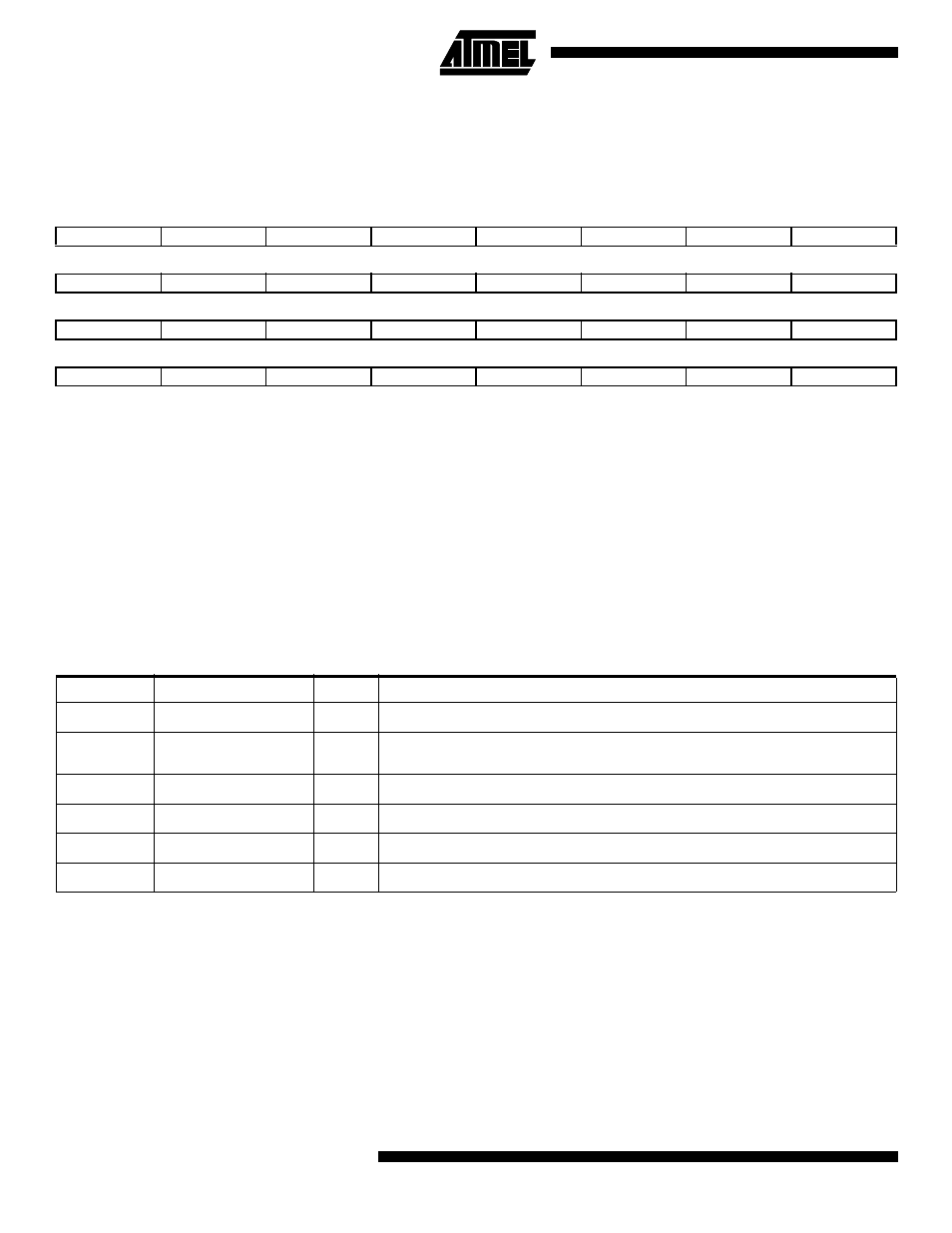
DRAM Common Configuration Register (DMC_CR)
The Common Configuration Register defines parameters which are common to the two DRAM regions.
Register Name:
DMC_CR
Reset Value is 0x00000000
•
DBW: Data Bus Width
When high, the DRAM data bus is 32 bits wide. When low, the DRAM data bus is only 16 bits wide. The DMC splits 32-
bit transfers into two 16-bit transfers which are transparent to the ASB.
•
BBR: Break Burst for Refresh
When this flag is high, the controller breaks long burst accesses every 32 CAS cycles if a refresh cycle is pending in
order to allow the refresh cycle to be performed. This prevents excessively long bursts from delaying refresh cycles.
•
ROR: RAS-only Refresh
When high, the CAS signal is held inactive (high) during normal DRAM accesses, thereby generating a RAS-only
Refresh cycle. This feature allows software to generate the row address and initiate the refresh cycle. When low, mem-
ory operations behave as normal and CAS is not inhibited.
DRAM Interface
31
30
29
28
27
26
25
24
–
–
–
–
–
–
–
–
23
22
21
20
19
18
17
16
–
–
–
–
–
–
–
–
15
14
13
12
11
10
9
8
–
–
–
–
–
–
–
–
7
6
5
4
3
2
1
0
–
–
–
–
–
ROR
BBR
DBW
Table 10. DRAM Interface
FPDRAM
Description
Type
Notes
NRAS[1:0]
Row Address Strobe
O
One strobe per DRAM region. Common to four bytes in each region
NCAS[3:0]
Column Address
Strobe
O
One strobe per byte. Common to both DRAM regions. Only NCAS[1:0] used
when Data Bus Width is 16
NWE
Write Enable
O
Common to both regions
NOE
Output Enable
O
Common to both regions
A[14:0]
Address Bus
O
Multiplexed row and column addresses
D[31:0]
Data Bus
I/O
D[15:0] used when Data Bus Width is 16