Dual-port mailbox, Dual-port ram – Rainbow Electronics AT75C310 User Manual
Page 122
AT75C310
122
Dual-port Mailbox
Communication between the asynchronous ARM7TDMI
and OakDSPCore are via the dual-port mailbox (DPMB). It
is assumed that each processor is running asynchronously
and that the coherency of communication is maintained by
robust software.
The DPMB consists of 512 bytes of DPRAM and some
memory-mapped registers that configure the DPMB and
act as semaphores. The DPMB sits on the ARM7TDMI
ASB bus and can be accessed by memory-mapped opera-
tions. Similarly, the DPMB also sits on the OakDSPCore
data bus and can be accessed by memory-mapped
operations.
Messages can be sent between the two processors by the
sending processor writing data to the DPRAM in the DPMB
and signalling via the semaphores. The data is subse-
quently read by the recipient processor. Individual
mailboxes are bi-directional with access permission con-
trolled by the semaphores. The message-passing protocol
can be configured for each mailbox as interrupt-driven or
polled in each direction.
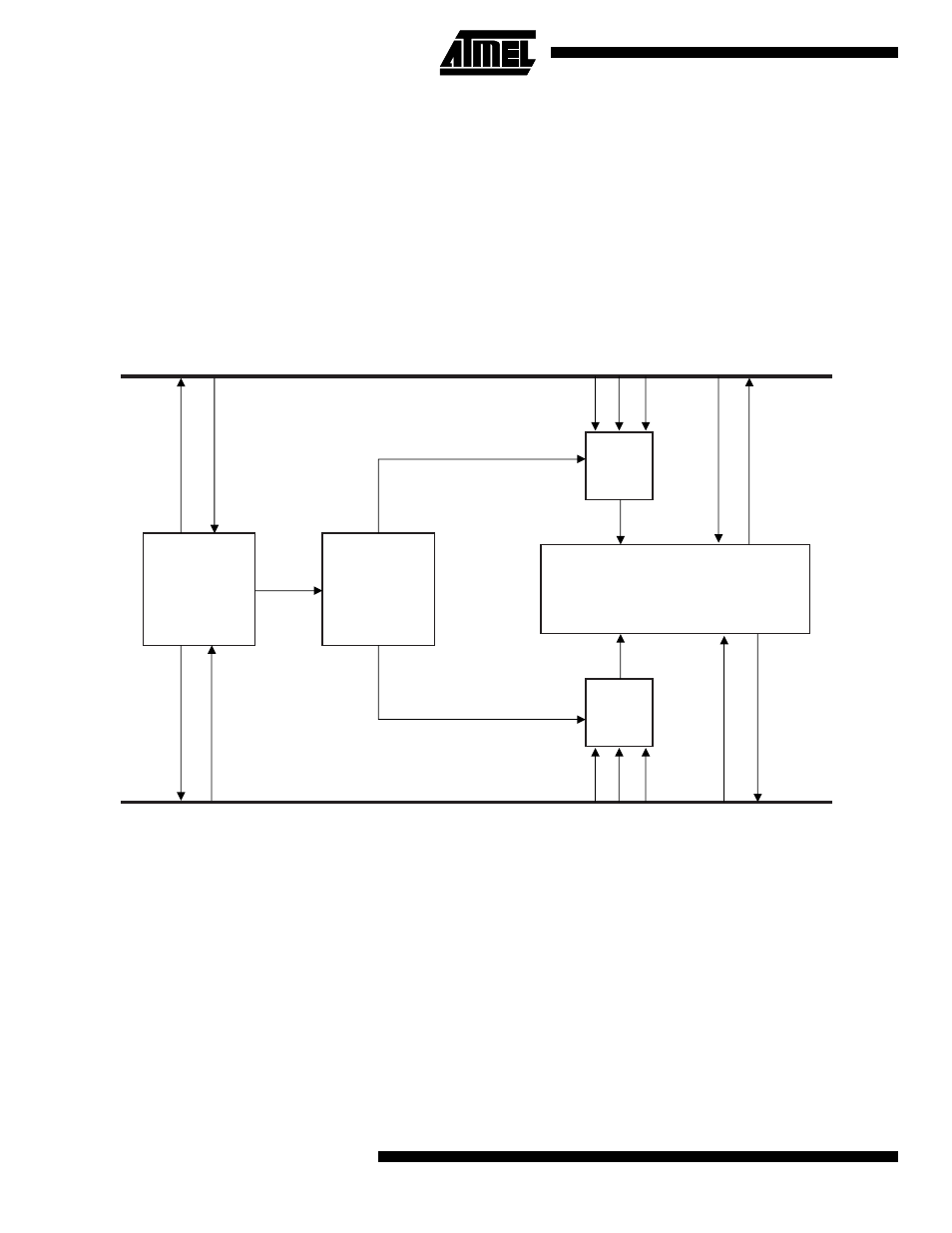
Figure 29. Dual-port Mailbox Block Diagram
Dual-port RAM
The major component of the DPMB is a dual-port RAM
(DPRAM). It consists of 256 x 16 bits of dual-port static
RAM. The DPRAM is divided into eight equal mailboxes,
each with its own semaphore register. The hardware imple-
ments locks so that both processors never have write
access to the same mailbox region. This protection mecha-
nism is based upon the values of the semaphores, which
must be maintained by the software.
If a processor attempts to access a mailbox to which it does
not have semaphore permission, then this access will be
ignored.
The DPMB supports word access from the ARM side pro-
vided the address is word-aligned, and half-word access
from both the ARM and Oak sides provided the address is
half-word-aligned. All other accesses will result in a data
abort being issued. The DPMB does not decode protection
information carried in AMBA output BPROT[1:0] and, as a
result, does not support Thumb-compiled code.
In order to reduce hardware, the minimum number of
address bits are used in decoding register and mailbox
addresses. This results in address aliasing. For the ARM
side, only address bits ba[5:2] and ba[9] are used in regis-
ter decode and bits ba[8:5] in mailbox decode. On the Oak
side, only address bits dxap[2:0] are used in register
decode and bits dxap[7:4] are used in mailbox decode.
Mailbox Memory
Access
Control
Access
Control
Protection
Mechanism
Semaphores
Logic
OAK Bus
ARM ASB
IRQ
IRQ
Control
Control
Enable
Enable
Rd
Wr
Rd
Wr
Data
Data
@
@
@
@