Memory map – Rainbow Electronics AT75C310 User Manual
Page 7
AT75C310
7
Memory Map
The memory map is divided into memory regions of 64
megabytes. The top seven memory regions are reserved
and subdivided for internal memory blocks or peripherals
within the AT75C310. The AT75C310 can define up to six
other active external memory regions by means of the
static memory controller and DRAM memory controller.
The memory map assumes default values on reset. Exter-
nal memory regions can be reprogrammed to other base
addresses. For details, see the sections “SMC: Static
Memory Controller” on page 15 and “DMC: Dynamic Mem-
ory Controller” on page 24. It should be noted that the inter-
nal memory regions have fixed locations that cannot be
reprogrammed.
There are no hardware locks to prevent incorrect program-
ming of the regions. Programming two or more regions to
have the same base address results in undefined behavior.
The ARM reset vector with address 0x00000000 is mapped
to internal ROM or external memory depending on the sig-
nal pin NDSRA/BOOTN. After booting, the ROM region can
be disabled and some external memory such as DRAM or
Flash can be mapped to the bottom of the memory map by
programming SMC_CS0 or DMC_MR0.
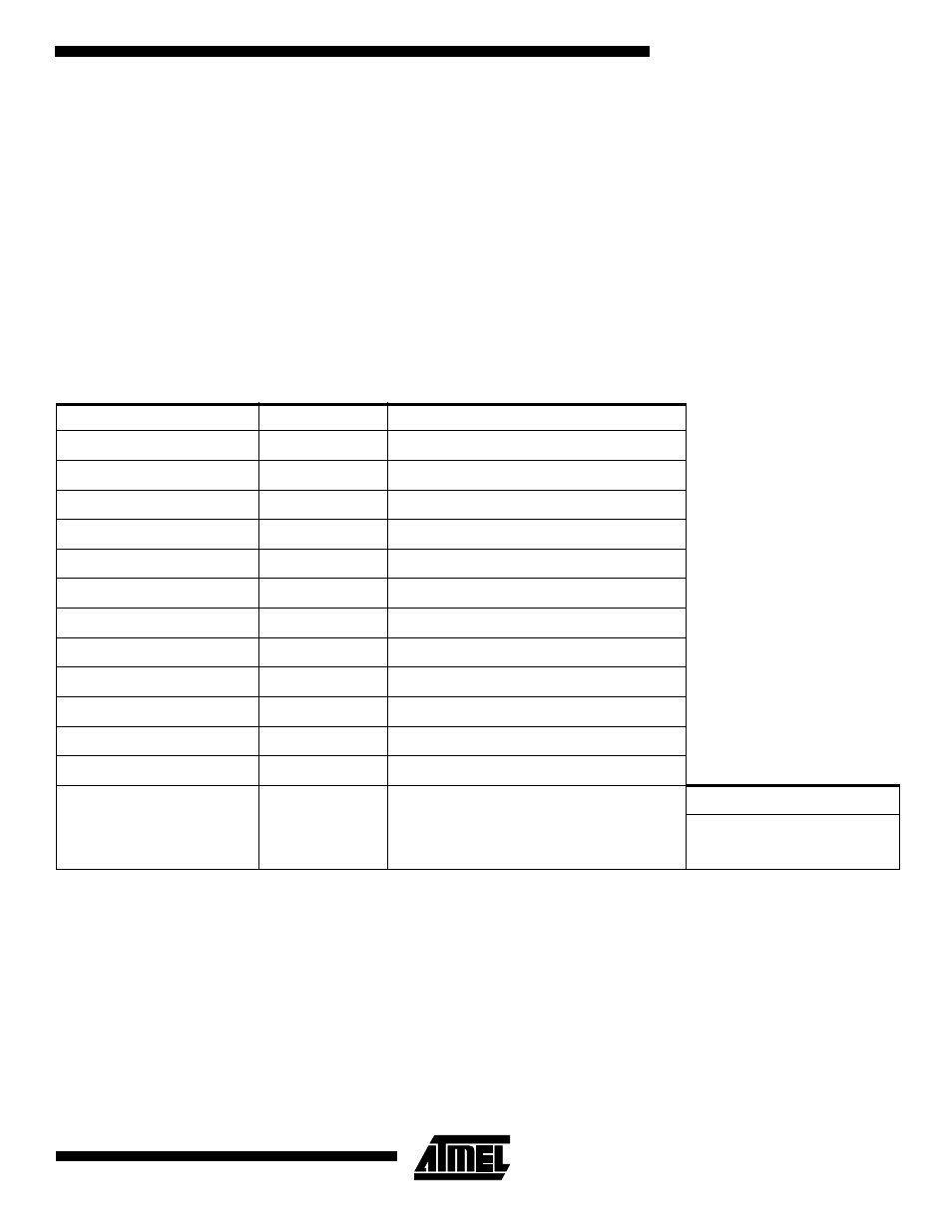
Table 3. Memory Map
Default Base Address
Region Type
Normal Mode
0xFF000000
Internal
Peripherals
0xFE000000
Internal
OAK B (24K x 16 Program SRAM)
0xFD000000
Internal
OAK A (24K x 16 Program SRAM)
0xFC000000
Internal
Reserved
0xFB000000
Internal
Dual-port Mailbox for Oak B (2K x 16)
0xFA000000
Internal
Dual-port Mailbox for Oak A (2K x 16)
0xF9000000
Internal
Boot ROM (1K x 16)
0x50000000
External
DMC_MR1
0x40000000
External
DMC_MR0
0x30000000
External
SMC_CS3
0x20000000
External
SMC_CS2
0x10000000
External
SMC_CS1
Boot Mode
0x00000000
External/Internal
SMC_CS0
0x000003FF
Boot ROM
0x00000000