Clocking – Rainbow Electronics AT75C310 User Manual
Page 10
AT75C310
10
Clocking
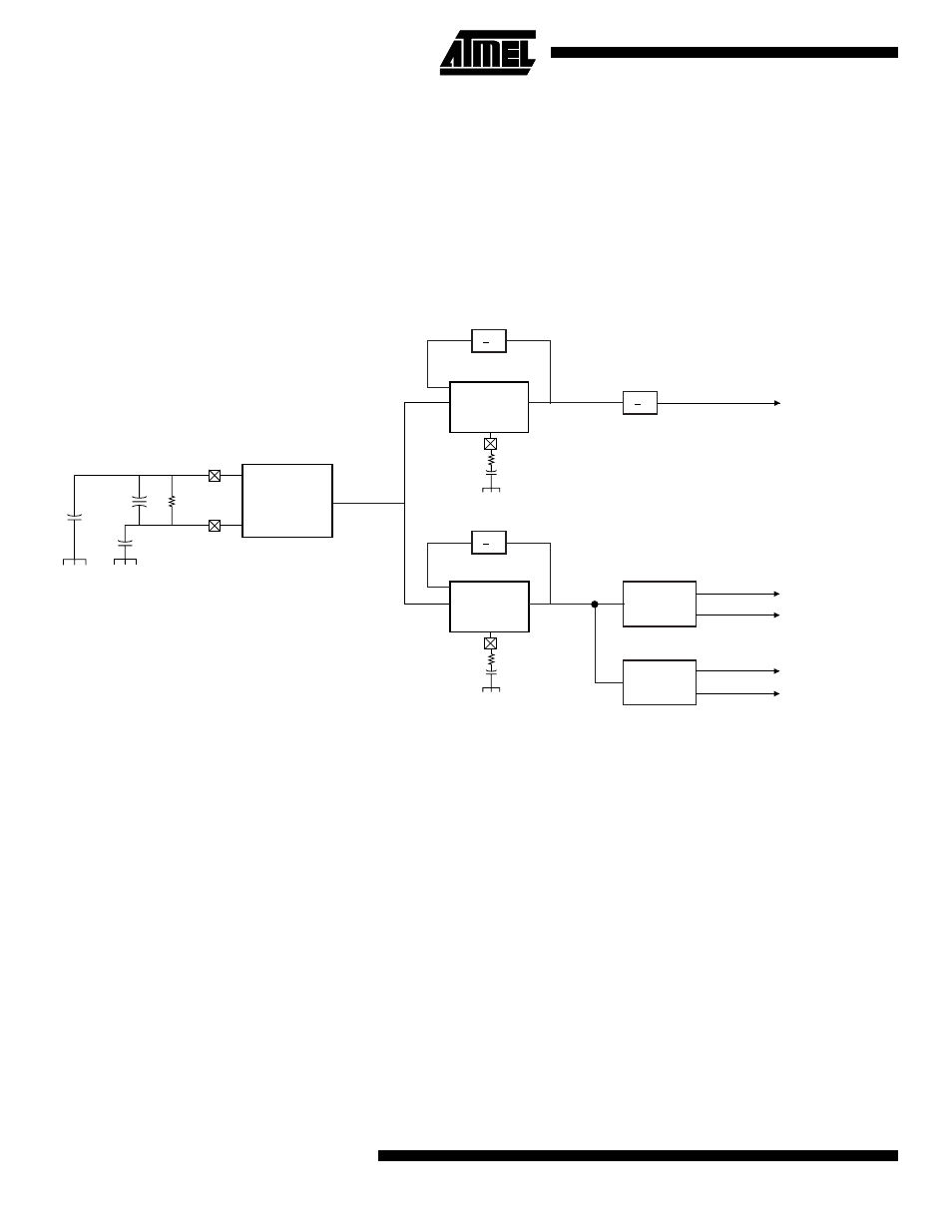
The AT75C310 uses an external 16 MHz crystal (XCLK)
and two on-chip PLLs to generate the internal clocks. One
PLL generates a 96 MHz clock that is divided down to pro-
duce the ARM clocks and the other produces an 80 MHz
clock used to generate the Oak and Codec interface
clocks.
The ARM core runs at 24 MHz whereas the DSP sub-
systems run at 40 MHz.
Note that there is a common synchronous mode where the
ARM and OAK systems both run from the Oak PLL. This
results in the ARM running at 20 MHz and the Oak at
40 MHz.
A block diagram of the clock circuitry can be seen below in
Figure 2.
Figure 2. AT75C310 Clock Circuitry Diagram
10 pF
XTALOUT
1 M
Ω
16
MHz
XTAL
10 pF
XTALIN
Oscillator
16 MHz
100
Ω
10 nF
XREF 96
PLL
100
Ω
10 nF
XREF 80
PLL
.. 6
.. 5
80 MHz
96 MHz
.. 4
Phase
Generator
Phase
Generator
24 MHz
40 MHz
40 MHz
40 MHz
40 MHz
ARM Clock
Core
DSP Subsystem A
Clocks
DSP Subsystem B
Clocks
- RC2000 (2 pages)
- Т7023 (12 pages)
- Т7024 (20 pages)
- RC2200 (17 pages)
- RF01 (26 pages)
- RC1090 (17 pages)
- U3741BM (32 pages)
- U3742BM (32 pages)
- RAM01 (7 pages)
- RF22 (92 pages)
- RC1180-MBUS (28 pages)
- RFM01 (8 pages)
- RF12B (36 pages)
- RC1290 (17 pages)
- RC2300-ZNM (1 page)
- RF12 (31 pages)
- T48C862-R3 (107 pages)
- RF02 (24 pages)
- T48C862-R8 (107 pages)
- RFM12 (10 pages)
- U3745BM (29 pages)
- T5744 (19 pages)
- RFM12B (10 pages)
- U2745B (9 pages)
- T48C862-R4 (107 pages)
- RA01 (19 pages)
- T5754 (11 pages)
- U2741B (9 pages)
- RFM02 (8 pages)
- RC2100 (22 pages)
- RF модули диапазона ISM (4 pages)
- T5761 (35 pages)
- BTM -17х (5 pages)
- ATA8401 (12 pages)
- BTM -22х (7 pages)
- AT86RF231 (180 pages)
- ATA5575M1 (7 pages)
- AT88RF1354 (50 pages)
- ATA5812 (90 pages)
- AT86RF401 (50 pages)
- AT76C551 (77 pages)
- BTM -250 (6 pages)
- AT75C320 (13 pages)
- BTM -140 (6 pages)