EVS ENGSoft v1.5 User Guide User Manual
Page 45
ENGSoft v1.5
This document is the exclusive property of OpenCube Technologies SAS and cannot be reproduced or distributed without prior authorization
45 / 63
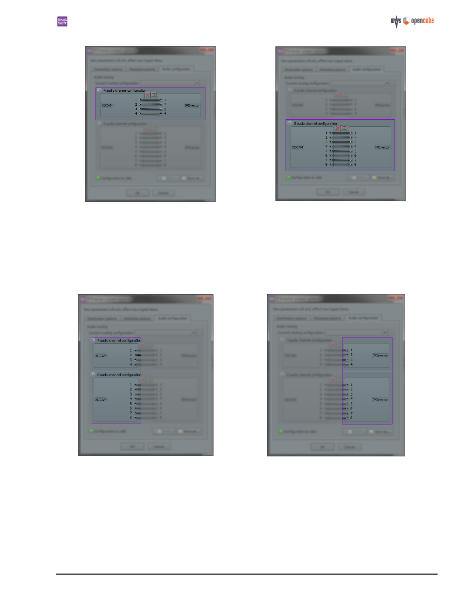
Figure 77: The four audio channel configuration layout
Figure 78: The eight audio channel configuration layout
The left side of an audio layout represents the ingest source, with the name of the source type displayed in the square. The
1-8 numbered buttons represent the source audio pins.
The right side of an audio layout represents the ingest destination, with the name of the destination subject type displayed
in the square. The 1-8 numbered buttons represents the destination audio pins.
The connection graph of the source pins to the destination pins is displayed in between. For example, a link connecting pin
#1 to destination pin #4 means that the source clip audio track #1 will be mapped to the destination clip audio track #4.
Figure 79: The source (XDCAM) side of the audio layout
Figure 80: The destination (IPDirector) side of the audio layout
Creating an audio routing configuration
To modify a configuration, all you have to do is to drag links between the source and destination pins. This will create new
connections.
- XFReader Version 2.6 - October 2013 User Manual (44 pages)
- Xfile Version 2.14 - January 2011 User Manual (190 pages)
- MulticamLSM Version 9.00 - March 2008 User's Manual (201 pages)
- XstoreSE (4 pages)
- XEDIO Importer Version 3.1 - January 2011 User Manual (34 pages)
- Xfile Version 1.01 - December 2006 User Manual (42 pages)
- XTract Version 1.01 - January 2011 User Manual (15 pages)
- MulticamLSM Version 8.03 - Dec 2006 User's Manual (156 pages)
- IPDirector Version 6.2 - June 2013 CHANNEL EXPLORER User Manual (48 pages)
- XS Version 11.02 - July 2013 Configuration Manual (204 pages)
- GX Version 1.00 - February 2011 User’s Manual (66 pages)
- LSM Connect (32 pages)
- MulticamLSM Version 10.01 - July 2009 Operating Manual (185 pages)
- XStoreSAN (4 pages)
- XTract Installation Note (1 page)
- MulticamLSM Version 10.03 - July 2010 Configuration Manual (97 pages)
- XTAccess Version 1.18 - July 2012 User Manual (109 pages)
- XEDIO Manager Version 3.1 - January 2011 User Manual (134 pages)
- EpsioAir (2 pages)
- XSense Version 10.04 - January 2011 Operating Manual (164 pages)
- MultiReview (2 pages)
- XEDIO Media Cleaner Version 3.1 - January 2011 User Manual (16 pages)
- XEDIO Media Cleaner Version 3.1 - January 2011 User Manual (18 pages)
- XEDIO Media Cleaner Version 4.1 - December 2011 User Manual (17 pages)
- XEDIO Playout Organizer Version 4.35 - August 2013 User Manual (36 pages)
- IPDirector Version 6.0 - November 2012 Part 2 User's Manual (92 pages)
- IPWeb Version 1.0 - June 2013 User Manual (76 pages)
- XEDIO Ingest Organizer Version 3.1 - January 2011 User Manual (22 pages)
- XTnano Version 11.02 - July 2013 Operation Manual (102 pages)
- Xfile Version 2.13 - July 2010 User Manual (192 pages)
- IP2Archive Version 1.2 - October 2012 User Manual (30 pages)
- XEDIO Importer Version 4.35 - August 2013 User Manual (38 pages)
- XTract Version 1.00 - May 2010 User Manual (16 pages)
- XEDIO Browse Version 3.1 - January 2011 User Manual (38 pages)
- EPSIO Version 1.63 - May 2011 User's Manual (73 pages)
- IPDirector Version 6.0 - November 2012 Part 10 User's Manual (30 pages)
- IPDirector Version 6.2 - June 2013 IPLOGGER User Manual (74 pages)
- IPDirector Version 5.8 - July 2010 Part 7 User's Manual (229 pages)
- XFLY Streamer Version 1.02 - April 2013 User Manual (25 pages)
- OpenCube MXFTK Version 2.6 - October 2013 User Manual (42 pages)
- IPDirector Version 4.3 - October 2007 Part 3 User's Manual (204 pages)
- IP2Archive Deep Archive Sync Version 1.1 - October 2012 User Manual (66 pages)
- XEDIO Playout Organizer Version 3.1 - January 2011 User Manual (29 pages)
- MulticamLSM Version 10.04 - January 2011 Configuration Manual (98 pages)
- XTAccess Version 1.19 - November 2012 User Manual (112 pages)