Electrical information, Vacuum pressure, Trim and flap indicators – Garmin G1000 Piper PA-46 Meridian User Manual
Page 105: Engine indication and crew alerting system
190-00763-01 Rev. A
Garmin G1000 Pilot’s Guide for the Piper PA-46 Meridian
91
ENGINE INDICATION AND CREW ALERTING SYSTEM
SY
STEM
O
VER
VIEW
FLIGHT
INSTRUMENTS
EICAS
AUDIO P
ANEL
& CNS
FLIGHT
MANA
GEMENT
HAZARD
AV
OID
ANCE
AFCS
ADDITIONAL
FEA
TURES
APPENDICES
INDEX
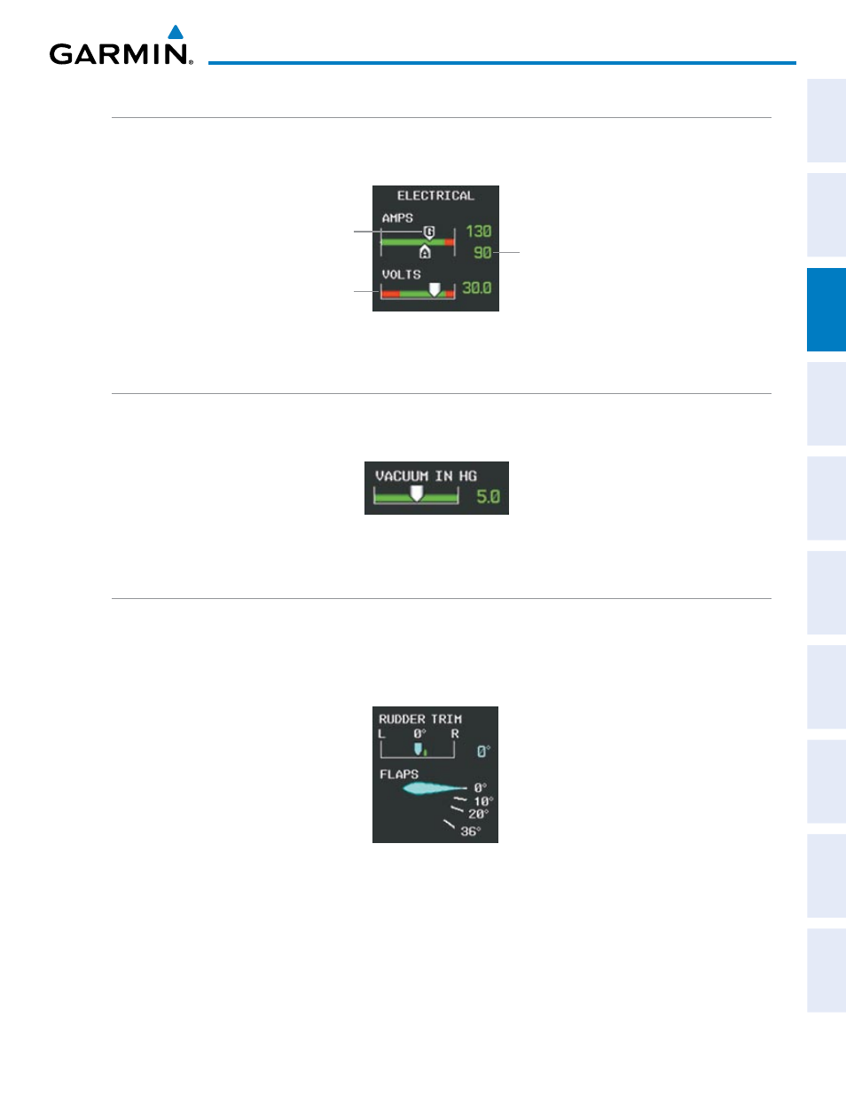
ELECTRICAL INFORMATION
DC current for the alternator (pointer labeled “A”) and generator (pointer labeled “G”) and voltage for the DC
bus are shown along color-coded horizontal scales, with readouts to the right.
Generator
Current
Bus Voltage
Alternator
Current
Figure 3-12 Electrical Display
VACUUM PRESSURE
The Vacuum Gauge displays the amount of suction in the vacuum system measured in inches of mercury (in
Hg).
Figure 3-13 Vacuum Gauge
TRIM AND FLAP INDICATORS
The Rudder trim indication is shown along a horizontal slide bar scale above the Flap indicator during normal
and reversionary display modes. The green band indicates takeoff position for the rudder trim. Flap position
is normally displayed beneath the rudder trim indication using a rotating pointer. Flap positions are labeled 0°,
10°, 20°, and 36°. In Reversionary Mode, only a digital readout is provided for flap position.
Figure 3-14 Rudder Trim and Flap Indications