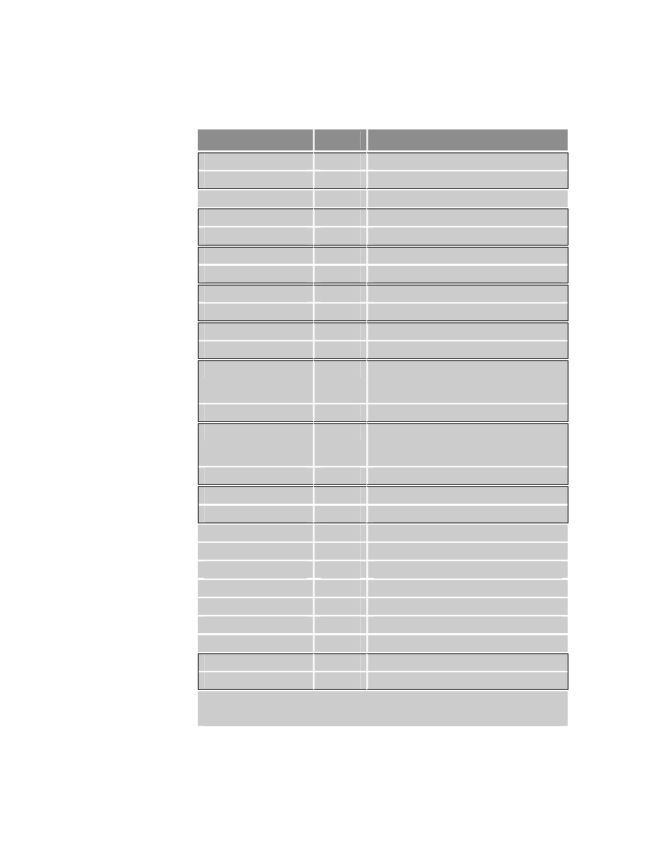
Table 29, Drive i, Connector pinout – Parker Hannifin 88-021610-01G User Manual
Page 69
Parker Hannifin
Chapter 3 Electrical Installation 69
Pinout—
DRIVE I
/
O
Connector
Note:
A box surrounding pins indicates a requirement for twisted pair wiring.
Signal
Pin
Description
ENABLE+
1
Drive Enable input anode
ENABLE–
21
Drive Enable input cathode
DGND
2
Digital ground
ENC A+
3
Encoder A Channel out
ENC A–
4
Encoder A Channel out
ENC B+
5
Encoder B Channel out
ENC B–
6
Encoder B Channel out
ENC Z+
7
Encoder Z Channel out (Index +)
ENC Z–
8
Encoder Z Channel out (Index – )
FAULT+ *
9
Fault Output collector
FAULT–
16
Fault Output emitter
STEP+
10
5V Differential compatible (RS-422
logic level compatible) position
command
STEP–
11
Position command return
DIRECTION+
12
5V Differential compatible (RS-422
logic level compatible) direction
command
DIRECTION–
13
Direction command return
AIN+
14
Analog ±10V current command
AIN–
15
±10V return
DGND
17
Digital Ground
RESET+
18
Drive Reset input anode
RESET–
23
Drive Reset input cathode
DGND
19
Digital Ground
DGND
20
Digital Ground
DGND
22
Digital Ground
DGND
24
Digital Ground
RS-232Rx/ RS-485+
25
RS-232Rx/ RS-485+ Half-Duplex
RS-232Tx/ RS-485–
26
RS-232Tx/ RS-485– Half-Duplex
* Opto is ON and conducting when no fault condition is present. When a fault occurs, the
opto turns OFF and the transistor does not conduct current. This simulates a normally
open relay. For more information, see Table 20.
Table 29
DRIVE I
/
O
Connector Pinout