Table 14 motor power fuse information, Motor power fuse information, Table – Parker Hannifin 88-021610-01G User Manual
Page 41
Parker Hannifin
Chapter 3 Electrical Installation 41
Warning —
You must connect the drive’s protective conductor terminal, marked
with the earth symbol
, to a reliable system Protective Earth.
Warning —
The drive’s connector strip terminals have hazardous voltages when
power is applied to the drive, and up to several minutes after power is removed.
Lower voltages may still be present for several minutes after power is removed.
During normal operation, these high voltage terminals must not be accessible to
the user.
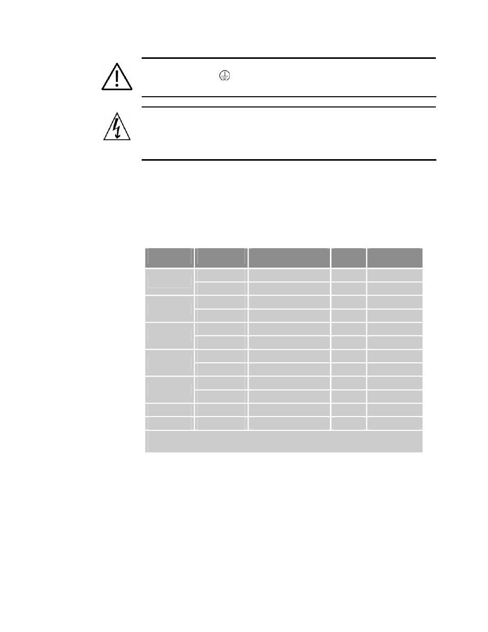
Motor Power Fuse Information
Aries drives have no user-serviceable internal fuses. For safety, you must
provide a fuse in each of the AC Mains Motor power input lines. To
determine the proper fuse type and size for your application, see Table 14.
(For fuse recommendations for Control-power input lines, see “Control Power
Supply” on page
Drive
AC Voltage
Fuse Style
Rating
Fuse Type
120 VAC
125 VAC Time Delay 10A
RK5 or better
AR-01xx
240 VAC
250 VAC Time Delay 10A
RK5 or better
120 VAC
125 VAC Time Delay 10A
RK5 or better
AR-02xx
240 VAC
250 VAC Time Delay 10A
RK5 or better
120 VAC
125 VAC Time Delay 20A
RK5 or better
AR-04xx
240 VAC
250 VAC Time Delay 20A
RK5 or better
120 VAC
125 VAC Time Delay 20A
RK5 or better
AR-08xx
240 VAC
250 VAC Time Delay 20A
RK5 or better
120 VAC
125 VAC Time Delay 30A
RK5 or better
AR-13xx
240 VAC
250 VAC Time Delay 30A
RK5 or better
AR-20xE*
240 VAC
250 VAC Time Delay 40A
RK5 or better
AR-30xE*
240 VAC
250 VAC Time Delay 40A
RK5 or better
*
The 40A fuse is recommended regardless of whether the input power is
single-phase or 3-phase.
Table 14 Motor Power Fuse Information