LOREX Technology NETWORK READY H.264 HIGH PERFORMANCE DIGITAL VIDEO SURVEILLANCE RECORDER LH300 Series User Manual
Lorex edge, Lh300 series, Model
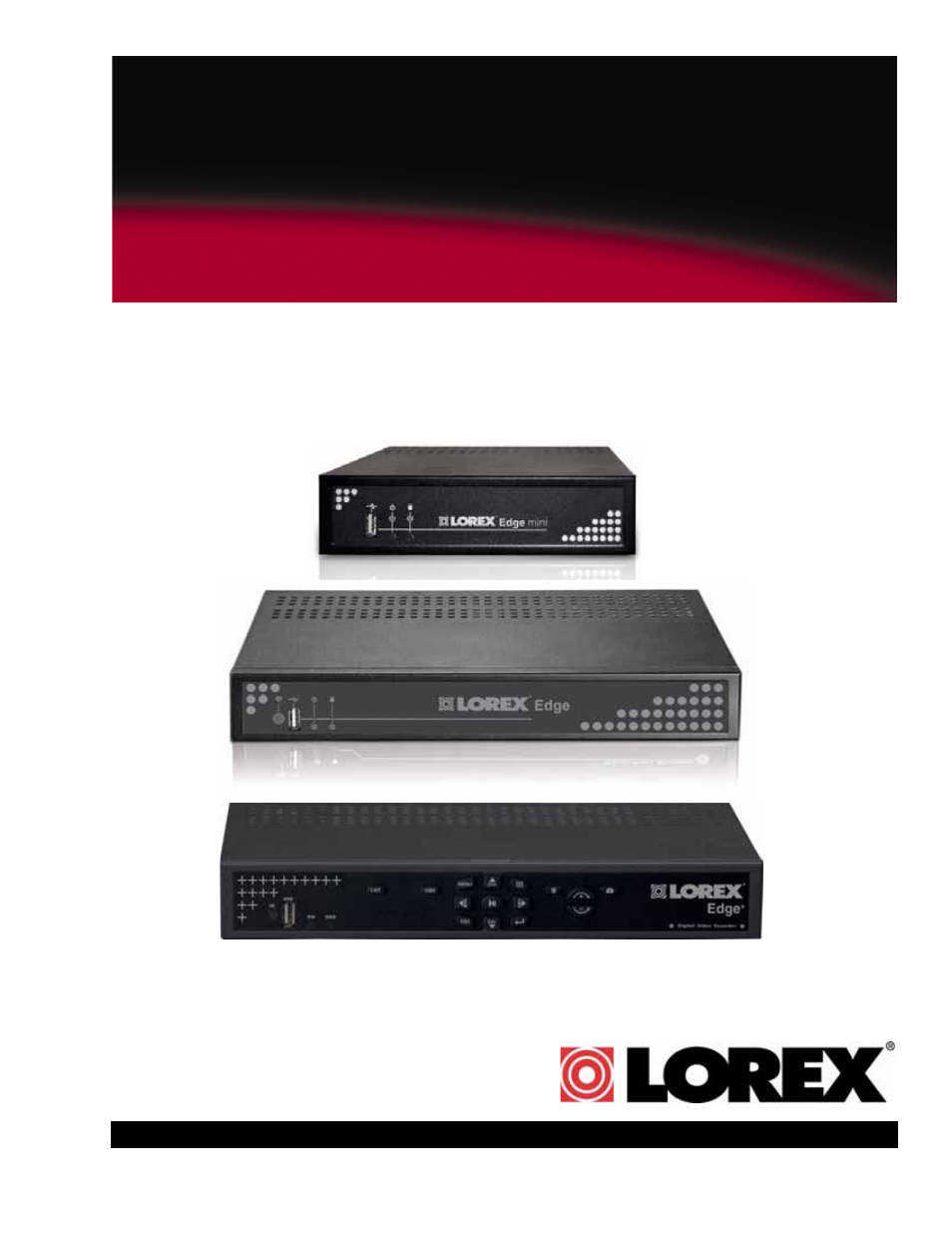
Table of contents
Document Outline
- 1. All warnings and instructions in this manual should be followed.
- 2. Remove the plug from the outlet before cleaning. Do not use liquid aerosol detergents. Use a water dampened cloth for cleaning.
- 3. Do not use this unit in humid or wet places.
- 4. Keep enough space around the unit for ventilation. Slots and openings in the storage cabinet should not be blocked.
- 5. During lightning storms, or when the unit is not used for a long time, disconnect the power supply, antenna, and cables to protect the unit from electrical surge.
- www.lorextechnology.com
- 1. Recording capacity may vary based on recording resolution & quality, lighting conditions and movement in the scene.
- 2. Easily mounts to the back of an LCD monitor with VESA standard mounting holes and an independent stand (monitor not included). Requires clear access to the 100 x100 mm VESA mounting holes.
- 3. DVI output only on 8/16-channel Edge models and 4/8/16 Edge+ models; VGA output only on 4-channel Edge and Edge mini models.
- 4. DVI to HDMI converter cable required (not included).
- 5. Not included in Edge mini.
- 6. Not included in Edge mini. Flex IR and remote control sold separately.
- 7. Instant Mobile Viewing on Blackberry™, iPhone™ or Windows Mobile™ 6.0 and above: selectable one channel live viewing. Mobile ...
- 8. Requires a high speed internet connection and a router (not included).
- 1. USB port: Connect a USB flash drive for data backup and firmware updates (download from website).
- 2. Power Indicator: LED indicator for system power.
- 3. HDD Indicator: LED indicator for internal hard drive.
- 1. GND: Ground port.
- 2. DC 12V: Port for 12V DC, 2.5A power adapter (included).
- 3. VGA: Port to connect a VGA monitor (not included).
- 4. Audio In: Input ports for audio enabled cameras. Audio Out: Output for two audio channels.
- 5. Video In: BNC input ports for 4 BNC cameras.
- 6. USB Port: Port for a USB mouse.
- 7. LAN: Networking port for a 10/100 Base-T RJ-45 network cable (included).
- 8. Flex IR port :Port for the Flex-IR Extender (Flex-IR Extender optional, not included).
- 1. IR Receiver: Internal IR receiver for the remote control.
- 2. USB port: Connect a USB flash drive for data backup and firmware updates (download from website).
- 3. Power Indicator: LED indicator for system power. When system is powered on, LED is lit red.
- 4. HDD Indicator: LED indicator for internal hard drive. When in continuous recording mode, LED pulses red.
- 1. Exhaust slots: Slots to let heat escape from the internal hard drive. Do not block. Allow for proper ventilation.
- 2. DC 12V: Port for 12V DC 2.5 A power adapter (included).
- 3. Alarm I/O: Input/output port for alarm / relay (D-sub 9 connector required-not included).
- 4. Audio In: Input ports for audio enabled cameras.
- 5. Video In: BNC input ports for 4 BNC cameras.
- 6. USB Port: Port for a USB mouse.
- 7. LAN: Networking port for a 10/100 Base-T RJ-45 network cable (included).
- 8. VGA: Port to connect a VGA monitor (not included)
- 9. Audio Out: Output for two audio channels.
- 10. IR: Port for the Flex-IR Extender.
- 11. Ground Port
- 1. Video In: BNC input ports for 8 BNC cameras.
- 2. Audio In: Input ports for audio enabled cameras.
- 3. Alarm I/O: Input/output port for alarm / relay (D-sub 9 connector required-not included).
- 4. Audio Out: Output for two audio channels.
- 5. DVI: Port to connect a DVI monitor (not included).
- 6. LAN: Networking port for a 10/100 Base-T RJ-45 network cable (included).
- 7. IR: Port for the Flex-IR Extender.
- 8. USB Port: Port for a USB mouse.
- 9. DC 12V: Port for 12V DC 3 A power adapter (included).
- 10. Ground Port.
- 1. Video In: BNC input ports for 16 BNC cameras.
- 2. Audio In: Input ports for audio enabled cameras.
- 3. Alarm I/O: Input/output port for alarm / relay (D-sub 9 connector required-not included).
- 4. Audio Out: Output for two audio channels.
- 5. DVI: Port to connect a DVI monitor (not included).
- 6. LAN: Networking port for a 10/100 Base-T RJ-45 network cable (included).
- 7. IR: Port for the Flex-IR Extender.
- 8. USB Port: Port for a USB mouse.
- 9. DC 12V: Port for 12V DC 3 A power adapter (included).
- 10. Ground Port.
- 1. IR Receiver: Internal IR receiver for the remote control.
- 2. USB port: Connect a USB flash drive for data backup and firmware updates (download from website).
- 3. Power Indicator: LED indicator for system power. When system is powered on, LED is lit red.
- 4. HDD Indicator: LED indicator for internal hard drive. When in continuous recording mode, LED pulses red.
- 5. LIST: Opens the Event List menu.
- 6. OSD: Show/hide the on-screen display.
- 7. Primary Controls:
- . MENU: Opens the system main menu.
- . : Press to open the Split-Screen Selection menu (8 / 16-channel only). From full-screen single channel view, changes display view to Quad split-screen (4-channel model only)
- . p/CH+: Move cursor in menus up; Channel Up.
- . u/FWD: Move cursor in menus right; during playback, increase forward playback speed (5X, 15X, 60X).
- . t/REW: Move cursor in menus left; during playback, increase reverse playback speed (5X, 15X, 60X)
- . 4/;: Start/pause forward playback.
- . q/CH-: Move cursor in menus down; Channel down.
- . ESC: Go back / exit menus.
- . : Confirm menu selections. Press twice in live viewing to access system information.
- . : Increase the value of selected menu option.
- . : Decrease the value of selected menu option.
- 1. DC 12V: Port for 12V DC, 2.5A power adapter (included).
- 2. DVI: Port to connect a DVI monitor (not included).
- 3. Audio In: Input ports for audio enabled cameras. Audio Out: Output for two audio channels.
- 4. Alarm Block: Input/output port for alarm / relay devices (i.e. PTZ cameras and sensors, not included).
- 5. Video In: BNC input ports for BNC cameras.
- 6. USB Port: Port for a USB mouse.
- 7. LAN: Networking port for a 10/100 Base-T RJ-45 network cable (included).
- 8. IR: Port for the Flex-IR Extender.
- 9. Ground Port.
- 1. Video In: BNC input ports for BNC cameras.
- 2. Audio In: Input ports for audio enabled cameras (not included). Audio Out: Output for two audio channels.
- 3. Alarm Block: Input/output port for alarm / relay devices (i.e. PTZ cameras and sensors, not included).
- 4. DVI: Port to connect a DVI monitor (not included).
- 5. LAN: Networking port for a 10/100 Base-T RJ-45 network cable (included).
- 6. IR: Port for the Flex-IR Extender.
- 7. USB Port: Port for a USB mouse.
- 8. DC 12V: Port for 12V DC, 3A power adapter (included).
- 9. Ground Port.
- 1. Video In: BNC input ports for 16 BNC cameras.
- 2. Audio In: Input ports for audio enabled cameras (not included). Audio Out: Output for two audio channels.
- 3. Alarm Block: Input/output port for alarm / relay devices (i.e. PTZ cameras and sensors, not included).
- 4. DVI: Port to connect a DVI monitor (not included).
- 5. LAN: Networking port for a 10/100 Base-T RJ-45 network cable (included).
- 6. IR: Port for the Flex-IR Extender.
- 7. USB Port: Port for a USB mouse.
- 8. DC 12V: Port for 12V DC, 3A power adapter (included).
- 9. Ground Port.
- Figure 1.3 Connect the Flex IR extender (Available as an optional accessory for the EDGE mini)
- a. Screw the provided mounting screws into the two top holes in the rear panel of your LCD monitor. Make sure the screws are only 3/4 of the way in; this will allow sufficient clearance to hang the system.
- b. Carefully place the system (front panel facing up) over the screws and slide down into place.
- a. Connect BNC cameras to the BNC ports on the rear panel.
- a. Connect the VGA / DVI cable (not included) from your LCD monitor to the VGA or DVI port on the rear panel of the system.
- a. Connect the included Ethernet cable to the LAN port on the rear panel of system; connect the other end of the Ethernet cable to an empty LAN port on your router (not included).
- a. Connect the Flex-IR extender to the port on the rear panel of the DVR. Position the Flex-IR extender near the front of your m...
- NOTE: The Flex-IR Extender is not required for normal operation. It may be necessary if there is not a clear line-of-sight between the DVR and the remote control.The Edge mini has an optional Flex IR extender and remote control.
- NOTE: Unless otherwise noted, all system functions described in this manual are achieved through mouse input.
- Figure 2.0 Connect a USB mouse to the USB port on the rear panel
- Figure 3.0 Remote Control
- 1. LIST: Open the Event List menu.
- 2. OSD: Show/hide the on-screen display.
- 3. Primary controls:
- . MENU: Opens the system main menu.
- . : Press to open the Split-Screen Selection menu (8 / 16-channel only). From full-screen single channel view, changes display view to Quad split-screen (4-channel model only)
- . p/CH+: Move cursor in menus up; Channel Up.
- . u/FWD: Move cursor in menus right; during playback, increase forward playback speed (5X, 15X, 60X).
- . t/REW: Move cursor in menus left; during playback, increase reverse playback speed (5X, 15X, 60X)
- . 4/;: Start/pause forward playback.
- . q/CH-: Move cursor in menus down; Channel down.
- . ESC: Go back / exit menus.
- . : Confirm menu selections.
- . : Increase the value of selected menu option.
- . : Decrease the value of selected menu option.
- Figure 4.0 Live viewing with on-screen display (4-channel model)
- 1. System Status Bar: Displays mode, password type, recording mode, language, and status of devices (HDD and USB).
- 2. Display: Full-screen single channel and Quad split-screen available in Live Viewing and Playback modes; if cameras are disconnected, channels display a blue screen with the text, "VLOSS."
- 3. HDD Status: Displays the recording space consumed on the hard disk (%) and the size of the pre-installed hard drive. For example, 250 GB.
- Figure 4.1 Single channel and Quad (4-channel model)
- Figure 4.2 Live viewing with onscreen display (16-channel model shown)
- 1. Display Screen: Shows live and recorded video-single, quad, and split-screen (16-split on 16-channel model only).
- 2. Camera Number/Title: You can set the display to show the Camera Number, Title, or show no title.
- 3. Channels: Displays channels on the system. Icons flash red to indicate recording is in progress.
- 4. Date/Time: Displays the date and time on the system.
- 5. HDD Status: Displays the recording space consumed on the hard disk (%) and the size of the pre-installed hard drive. For example, 250 GB. This reading is an approximation.
- 1. Click to open the Split-Screen Selector. If you are in full-screen, click to view quad, then click again to open the Split-Screen Selector. Grid configurations appear in circles onscreen.
- 2. Click a grid configuration for live viewing:
- Figure 4.4 Split-Screen Selector (8-channel)
- Figure 4.7 The channel menu.
- 3. While holding left-click, move the mouse to the left or right to change the channel number.
- 4. Release left-click on the mouse to assign the new channel.
- 1. Click to open the Main Menu.
- 2. Click to open the Setup menu.
- 3. Click Date/Time Setup and configure the following options:
- 4. Click Exit/Update. The new date and time are saved; the system returns to the Setup menu.
- 5. Right-click to exit until all menus are closed. The date and time will appear on the bottom-left corner of the screen.
- Figure 5.0 Clock menu
- Figure 6.0 Playback display view
- 1. From the main screen, click . Playback mode opens.
- NOTE: If toolbar is not visible, first click .
- 2. Select and change the date, month, year, time, and/or frame for playback and click .
- 3. During playback, you have access to the following:
- 4. Click any channel to view the selected channel in full-screen; or click , , , .
- 5. Click anywhere in the playback bar to set a playback marker. Playback Markers can be used for faster searching in the Event List. See “Playback Markers” on page 20.
- 6. Right-click anywhere on the screen to exit.
- Figure 6.1 Playback display view
- Figure 7.0 Event List
- 1. Channel Filter: View data from all, or individual cameras.
- 2. Smart Search: Filter events through Smart Search icons.
- 3. Event Details: View details for the event, including date & time and event source.
- 4. Events: List of recorded events on the system.
- 5. Active Toolbar Buttons: While in Event List, use Play/Pause, Trash (delete), and C (Escape).
- NOTE: The Escape button is only on Edge and Edge mini models. Screenshot button appears on 8/ 16-channel models.
- 16-channel models
- Figure 7.1 Smart Search Icons
- Event Number
- 1. From the main screen, click . The Event List opens.
- 2. Under Channel Filter, click to view events for ALL channels, or click the Channel icons to view events from individual channels.
- 3. Click the Smart Search icons to sort the data according to the following:
- NOTE: USB backups appear at the top of the list if the USB flash drive with saved backup data is connected.
- NOTE: You cannot begin playback after clicking or
- NOTE: If toolbar is not visible, first click .
- NOTE: Click for Edge 8/16-channel models.
- 3. Under Channel Filter, click to view events for ALL channels, or click the Channel icons to view events from individual channels.
- 4. Click any of the Smart Search icons to filter your search.
- 5. Scroll up/down to view the events on the list.
- 6. Click an event from the Event List and then click . Playback begins for the selected file.
- NOTE: You cannot begin playback after clicking or .
- 1. Connect a USB flash drive (not included) to the USB port on the front panel of the system. Format the USB flash drive if you have not already done so. For more details, see “Formatting the USB Drive” on page 38.
- 2. If you want to capture a point in live viewing or playback, select the display view for the screenshot: single, quad, or split-screen.
- 3. Click . The screenshot will appear in the centre of the main display, followed by the file name. Screenshots are saved to the Picture folder on the USB flash drive.
- Figure 7.3 Screenshot being taken on the system
- Figure 7.4 AutoPlay screen
- Figure 8.0 Login with your user ID and password using the Password Wheel
- 1. Click to open the Main Menu. If necessary, login to the system.
- 2. Click . The Setup menu opens.
- 3. Click Password Enable and scroll up/down to select O to enable passwords, or X to disable.
- 4. To exit, right-click until you return to the main screen.
- 1. Click to open the Main Menu.
- NOTE: In older firmware models, click .
- Figure 8.1 Password change
- 7. To exit, right-click until you return to the main screen.
- NOTE: If passwords are enabled on the system, you need to select your user ID and enter the four-digit numerical password to open the Main Menu. See “Managing Passwords” on page 27.
- When navigating menus:
- Left mouse button: Click to select menu options
- Scroll-Wheel: Scroll up/ down to change values for selected options
- 3. Record: Configure recording parameters for Alarm/Motion recording, and working/non-recording; adjust video quality, resolution, set record mode, schedule, and format the hard drive
- 4. Alarm: Configure alarm, motion, and video loss settings.
- 5. Backup: Set backup parameters; format connected USB flash drive.
- 6. LAN: View/configure networking settings.
- Figure 10.0 Camera menu
- 1. From the Main Menu, click . The Camera menu opens.
- 2. Select Color Adjust.
- 3. Click camera 1, 2, 3, or 4. The video settings menu opens.
- 4. Configure the following:
- 5. Scroll up/down to increase/decrease the value for the selected option.
- 6. To save your settings, right-click until you return to the main screen.
- 1. From the Main Menu, click . The Camera menu opens.
- 2. Click on Sequence Time.
- 3. Scroll the mouse wheel to adjust the sequence duration.
- NOTE: Sequence Time refers to the time the camera channel changes to the next camera channel (in single channel view).
- Figure 11.0 System Setup
- Figure 11.1 System Languages
- Figure 11.2 System information
- Figure 12.0 Record menu
- Figure 12.1 Frame rates for NTSC and PAL
- Figure 12.2 Set image quality: 1 basic ~ 5 excellent
- Figure 12.3 Record menu (8/16-channel)
- Figure 12.4 Frame Rate menu (8/16-channel only)
- Figure 12.5 Frame rates for NTSC and PAL
- Figure 12.6 Set image quality: 1 basic ~ 5 excellent
- Figure 12.7 Recording Schedule
- Figure 12.8 Storage calculator
- Figure 12.9 Storage calculator
- Figure 13.0 Alarm menu (4-channel)
- Figure 13.0b Alarm Input & Output menu
- Figure 13.0c Alarm-In Setup menu
- Figure 13.0d Alarm-Out Setup menu
- Figure 13.1 Alarm menu (8/16-channel)
- Figure 13.2 Alarm Input & Output menu
- Figure 13.3 Alarm-In Setup menu (8/16-channel only)
- Figure 13.4 Alarm-Out Setup menu
- . VLoss Response Time: Select the time (in seconds) for the system to record prior to a triggered event: 0, 3, 5, 10, 30, 60, 120, 180, or Infinite
- . Enabled (yellow)
- 1. From the Alarm menu, click Motion Enable. The text, "Motion" will appear on-screen when motion is detected on the respective camera.
- 2. Choose a camera for motion detection and select O.
- 3. Click Motion. Select the camera you want to configure motion detection. The motion grid appears for the selected camera.
- . VLoss Response Time: Select the time (in seconds) for the system to record prior to a triggered event: 0, 3, 5, 10, 30, 60, 120, 180, or Infinite
- Figure 13.6 Select the camera for motion detection (4-channel)
- 4. Click within the grid to enable/disable individual motion cells. Enabled cells are light green; disabled cells are clear.
- . Motion Detection Disabled
- 5. Click the Sensitivity bar at the bottom of the screen. Scroll up/down to increase/ decrease the sensitivity for the motion cells from 0~100. The higher the number, the greater the sensitivity.
- NOTE: Sensitivity applies to all cells. If the Sensitivity bar is not visible, click .
- NOTE: The system supports most brands of USB flash drives from 128 MB ~ 8 GB.
- Figure 14.0 Backup menu
- Figure 14.1 Confirm formatting
- 1. Connect a formatted USB flash drive to the USB port on the front panel.
- NOTE: Do not connect a USB flash drive to the USB port on the rear panel. Only the port on the front panel has been designed for backup data transfer.
- 2. From the Main Menu, click . The Backup menu opens.
- 3. Click Start Time, and select the date, month, year, and time to begin the backup. Event Markers will appear in the Time Bar as you scroll through the date and time.
- 4. Click Stop Time, and select the date, month, year, and time to begin the backup.
- NOTE: Event Markers will appear in the Time Bar as you set through the Start and Stop times.
- 5. Click Select Channel, and select a channel for backup.
- 6. Click Save. Backup begins-the on-screen counter displays the progress of the transfer based on the selected start and stop times.
- 7. To cancel Backup, right-click until you return to the main screen. Please allow a few moments for the system to exit.
- NOTE: Backup may take several moments depending on the size of data being transferred.
- 1. Click to open Event List.
- 2. Click from the Smart Search event filter.
- 3. Select the file and click . The backup file should begin playing.
- 4. To exit, right-click until you return to the main screen.
- 1. On your PC, open the folder where you saved the MOV file (by default, C:\). By default, converted files use the following naming convention: bv3.mov
- 2. Double-click the file to open it in QuickTime Player.
- 1. Right-click on the backed up video file you wish to view.
- 2. Move the cursor to Open With.
- 3. Click on Choose Default Program.
- 4. Under Recommended Programs, select QuickTime Player and then click OK.
- NOTE: For the latest version of QuickTime, go to www.apple.com/quicktime/download/
- NOTE: Some networking knowledge is required when adjusting options in the LAN menu.
- Figure 15.0 LAN menu
- 1. Select the following, and use the scroll-wheel to change values:
- 2. To save your settings, right-click until you return to the main screen.
- NOTE: DCHP allows you to quickly connect to your network by obtaining an IP address from the router. After the initial setup, we...
- NOTE: For added security, we strongly recommend changing HTTP port 80 on the system to any desired port not blocked by your Internet service provider (ISP). For details on changing ports on your system, see “Changing Ports On Your System” on page 42.
- Figure 15.1 : Easy Connect menu.
- Figure 15.2 : Log File window.
- Figure 15.3 LAN Passwords
- 1. Select LAN Password and use the Password Wheel to login as the administrator (by default - 4 channel: ID: 2; password: 2222/ 8/16 channel: ID: 3; password 3333).
- 2. Only the administrator can edit and manage LAN passwords.
- 3. Select the following, and use the Password Wheel to change the LAN user ID and password:
- 4. To save your settings, right-click until you return to the main screen.
- 1. Connect a USB flash drive to the USB port on the front panel of the DVR and format (see “Formatting the USB Drive” on page 38.) Once formatting is complete, remove the USB flash drive and connect it to a USB port on your computer.
- NOTE: The system creates two folders on your USB drive: Picture and Movie.
- 2. In your web browser, visit your DVR manufacturer’s website and download the free firmware upgrade.
- 3. Copy the firmware file to the connected USB flash drive-do not place the file in either the Picture or Movie folder. Once the file transfer is complete, remove the USB flash drive from your computer.
- 4. Disconnect the power cable to power off your DVR and connect the USB flash drive. Reconnect the power cable.
- 5. The system will detect the USB drive and new firmware and begin the upgrade process. The system will prompt you when the upgrade is complete.
- 6. Remove the USB flash drive from your DVR and power off your system.
- 7. Power on the system. The system is now upgraded with the new firmware.
- If you change the default port on the system from 80 to a different value, you MUST enter http:// and the port number after the IP address.
- For example, if you change your port number from 80 to 85, you MUST enter port 85 after the IP address, i.e. http://192.168.5.120:85.
- There is a semi-colon after the IP address, followed by the port number.
- Figure 15.4 Change the HTTP port
- 4. Right-click to exit and save your settings (or press the ESC button on the remote control.
- 5. Disconnect the power cable from the rear panel of the system. Let the system power-down for 15~20 seconds and then reconnect the power cable.
- 6. To confirm that the new port number is saved on your system, the button twice on the remote control to view the System Information.
- Figure 15.5 Confirm the new HTTP port
- Figure 15.4 Enter :85 at the end of the IP address
- Figure 15.6 Login with your LAN ID and password
- Remote Viewing:
- NOTE: We strongly recommend registering for Lorex’s free DDNS service prior to using remote viewing. For details, see “Setting Up DDNS” on page 76.
- 1. From a PC on your local network, open Internet Explorer.
- 2. In the address bar, enter http://, then the IP address of your system, followed by a semi-colon, then the port number (i.e. :85) . For example, http://192.168.1.89:85
- 3. Enter your LAN ID and password to log in to your system.
- 4. Click the Setup button and then click Network.
- 5. Click DDNS. Enter your DDNS information from the confirmation email and click Submit. For complete details on entering your DDNS information, see “Enabling DDNS on your system” on page 77.
- 6. Reset your system by disconnecting the power cable from the rear panel of the system. Let the system power down for 15~20 seconds and then reconnect the power cable.
- 7. To confirm that the DDNS information is saved on your system, press the button twice on the remote control to view the System Information.
- Figure 15.7 Your DDNS sub-domain should appear in System Information
- Figure 15.7 Enter :85 at the end of the DDNS URL
- Figure 15.8 Login with your LAN ID and password
- Figure 16.0 DVR Netviewer Main Screen (8/16-channel)
- Figure 17.0: Four channel Netviewer.
- Figure 17.1: Sixteen channel Netviewer.
- 7
- 1111
- 8
- 2222
- 9
- 3333
- Figure 19.0 DVR Netviewer main screen
- 1. Display screen: Displays channels in single channel full-screen, or all channels in quad split-screen.
- 2. Date/Time: Present date and time on the networked system.
- 3. Modes:
- . LIVE: Click to view live, streaming video; view single channels in full-screen, or view all channels in quad split-screen.
- . PLAYBACK: Click to view recorded video from the system. Select channel and enter date and time; playback controls appear when Playback mode selected.
- . BACKUP: Click to save recorded video data to your PC.
- . SETUP: Click to open the Setup menu. (Not available on Safari (Mac) ).
- NOTE: PTZ function is not available in Netviewer.
- Figure 19.1 DVR Netviewer main screen (16-channel shown)
- 1. Display screen: Displays channels in single channel full-screen, or all channels in quad split-screen.
- 2. Date/Time: Present date and time on the networked system.
- 3. Modes:
- . LIVE: Click to view live, streaming video; view single channels in full-screen, or view all channels in quad split-screen.
- . PLAYBACK: Click to view recorded video from the system. Select channel and enter date and time; playback controls appear when Playback mode selected.
- . BACKUP: Click to save recorded video data to your PC.
- . SETUP: Click to open the Setup menu. (Not available on Mac)
- NOTE: PTZ function is not available on Netviewer.
- Figure 20.0 Live Viewing controls (4-channel shown)
- Figure 21.1 Playback controls .
- Figure 21.2 Pop-Up Calendar PC and Mac version.
- 1. Click 34to change the month.
- 2. Select a date.
- 3. Click 56to set the time.
- 4. Click SET. The pop-up calendar closes.
- 5. Click , , , to control playback.
- NOTE: Only the system administrator (by default, ID 9, password 9999 ) may use the Backup function of DVR Netviewer.
- NOTE: You may be prompted to install the ActiveX plug-in for Backup to function properly.
- Figure 22.0 Backup controls .
- Figure 22.1 Install the Project1.cab file
- NOTE: You may need to log back into your system via DVR Netviewer after the Backup process.
- 1. Click the (BACKUP) button.
- 2. Click the Channel buttons to select the channel you want to back up.
- 3. Under Start Time, click to open the pop-up calendar and enter a date and time. Click the SET button.
- 4. Under Stop Time, click to open the pop-up calendar and enter a date and time. Click the SET button.
- 5. Click Start to begin backup. The file is saved to C:\DVR_Backup (PC) , Macintosh HD > DVR_Backup (Mac)
- NOTE: Backup files carry the file extension .mov; QuickTime Player is required to view MOV files. Windows Media player can also play .mov files in Windows 7.
- NOTE: You may need to log back into your system via DVR Netviewer after the Backup process.
- Figure 22.2 Backup progress (8 channel shown)
- Figure 23.0 System Status in Setup menu.
- Figure 23.1 System Status in Setup menu (8/16-channel)
- Figure 23.2 PPPoE menu (8/16-channel)
- Figure 23.3 DDNS menu.
- Figure 23.4 Enter only the first portion of your domain name .
- 5. Click Apply to save your settings or click Clear to exit without saving.
- 6. To ensure your DDNS settings are saved on your system, disconnect the power cable from the rear panel of your system. Allow the system to power down for 15~20 seconds. Reconnect the power cable.
- NOTE: Please allow 10~15 minutes for the DDNS servers to update with your new DDNS address. This is normal for the DDNS system.
- Figure 23.5 System Status (8/16-channel).
- Figure 23.6 Default email notification setup (8/16-channel only)
- 1. Under Send Mail Status, select Default.
- 2. In the From Your Email field, enter the sender’s email address.
- 3. In the Interval drop-down menu, select the duration the system will pause sending notifications before sending out a new e-mail alert.
- 4. In the Send To Email fields, enter the recipient’s email address.
- NOTE: You must enter a sender and recipient email address for mail notification to work.
- NOTE: If you have made a mistake with either email addresses, you will not receive the test notification.
- NOTE: If you want to use your own SMTP server, select ON from the Send Mail Status drop-down menu. Enter the address of your SMT...
- NOTE: 8/16 channel models send e-mail notifications with a screen capture. 4 channel models send text notifications only.
- Figure 23.7 Camera title setup (8/16-channel only- 16-channel shown)
- 1. Click the Title tab.
- 2. In the Channel fields, enter the new name/title for the camera. For example, Parking Lot 1, Front Door, etc.
- 3. Optional: Click Font Option to select the font and font style.
- 4. Optional: Under Font Size, click the drop-down menu and select X-Large, Large, Medium, Small, or X-Small. You can also drag the slider to adjust the font size.
- 5. Optional: Click the drop-down menu below the font options to select the language for the camera titles.
- 6. Click Save File to save your camera title configuration to your PC. Files are saved as MOV files.
- 7. Click Apply to save the new title to your system.
- 8. Refresh your screen by changing the display mode (single, quad, split-screen) to see the titles.
- NOTE: Experience with routers and networking are recommended if configuring the network functions of the system.
- . Edge DVR System
- . PC with Internet Explorer 6 or later OR Intel-based Mac™ with OSX and Safari web browser (version 4 or later)
- . Router and high speed internet (not included)
- Local Vs Remote Viewing
- 1. Power off your system by disconnecting the power cable from the rear panel.
- 2. Connect an Ethernet cable (included) to the LAN port on the rear panel of the system. Connect the other end of the Ethernet cable to an empty LAN port (usually numbered 1~4) on your router.
- 3. Reconnect the power cable to power the system back on.
- 4. Locate your system’s IP address and port number.
- NOTE: Make sure you have connected the DVR to your local or wide area network via the LAN port on the rear panel of the system.
- Figure 24.2 System information.
- 3. To exit, right-click or click "C" in the menu bar until you return to the main screen.
- 1. Open Internet Explorer or Safari (Mac users)
- 2. Enter http://, then your system’s IP address, followed by a semi-colon, followed by the HTTP port number. For example, enter http://192.168.11.89:80 into the web browser.
- 3. Enter the system’s login and password information, and then click Login.
- NOTE: This method only works for LOCAL VIEWING ONLY. If you wish to access your system from a remote location, you must setup Easy Connect, or enable DDNS.
- 1. Open Internet Explorer.
- 2. In the address bar, enter the IP address of your system. (Press the Enter button on the remote twice to open the system information window.
- 3. In the ID and password fields, enter your LAN user ID and password and click LOGIN. If you enter an incorrect user ID or password the login page will refresh and the text fields will clear.
- Figure 24.4 Login screen.
- Figure 24.5 Click the ActiveX attention bar
- Figure 24.6 Select Install ActiveX Control
- Figure 24.7 Login window (Mac).
- Figure 24.8 Safari plug-in prompt.
- Download version 10.5 or 10.6 of the firmware accordingly to your operating system version.
- Double-click to run plug-in
- Figure 24.10 Plug-in installation.
- 7. Restart Safari and re-login to Net Viewer to begin viewing.
- 1. Create an Easy Connect account.
- 2. Enable Easy Connect on your system.
- 1. Port forward port 80 to your router using one of the following:
- 2. Create a Lorex DDNS account.
- 3. Enable DDNS on your system.
- Intended Use
- Backup button
- Figure 25.1 : Format prompt screen.
- 8. Remove the USB flash drive from the DVR when formatting is complete.
- 1. Go to www.lorexcctv.com and search for LH3xx (where xx is your model #). Download the latest firmware relevant to your model number.
- NOTE: 4-channel firmware is different from the 8 & 16-channel firmware.
- NOTE: Firmware ends in a .rom extension.
- 1. Power down the DVR by unplugging the power cord from the DVR.
- 2. Insert the USB flash drive into the DVR.
- 3. Turn on the DVR by plugging the power cord into the DVR.
- 4. Wait for the DVR to detect the USB flash drive. The firmware upgrade automatically begins.
- 5. Click Yes to begin the firmware upgrade. Wait for the firmware upgrade to finish.
- Click Yes to begin firmware upgrade.
- LAN icon
- A blue "O" indicates Yoics is enabled.
- A red "X" indicates Yoics is disabled.
- You must connect your DVR to a router connected to the internet before registering a Yoics account.
- This ensures that upon account activation, Yoics will automatically detect your DVR.
- Figure 25.5: Yoics registration screen.
- Figure 25.6: Yoics device detection pop-up.
- Enter desired name of your DVR here.
- Click Install ActiveX Control.
- Click Install to install ActiveX.
- NOTE: The connection times out after 15 minutes to conserve your bandwidth. Simply re-login to your account to begin remote viewing.
- NOTE: For added security, we strongly recommend changing HTTP port 80 on the system to any desired port-the port must not blocked by your Internet service provider (ISP).
- Click Next
- Select the users who can see the software shortcut (optional)
- Finish button
- 6. Double-click the Lorex Auto Port Forwarding shortcut ()from your desktop to start the program.
- 1. Your router’s model number and version number
- 2. Your router’s user name and password
- 3. Your Lorex device’s IP address
- 4. Your Lorex device’s port numbers that require port forwarding
- 1. Click the Language drop-down menu and select a language (English, French, Spanish). Click the Start button to continue.
- Start button
- Click to check for multiple routers
- Search and Auto detect button
- Enter your Lorex device’s IP
- Update Router button
- 2. Close the update window when the update finishes.
- 1. Click the Test Your Connection button.
- NOTE: Ensure that Internet Explorer is your system’s default internet browser.
- NOTE: A window opens that prompts you to enter in your DVR’s user name and password (do not enter your DDNS log in information).
- NOTE: ActiveX warnings may appear. Accept all ActiveX installation warnings to connect to your system.
- "2" indicates two routers have been detected
- Figure 28.0 Create a DDNS account
- 2. Complete the Account Information fields with your personal information. Complete the Warranty Information with your purchase details (optional).
- 3. Complete the System Information fields:
- 4. Once the information has been entered, click Create New Account.
- 5. Your Account information will be sent to you at the email Address you used in Step 2.
- Figure 28.2 System information
- Figure 29.0 DDNS setup in DVR Netviewer
- 1. Connect the system to your router.
- 2. Obtain your system’s IP number and Port number.
- 1. Open Internet Explorer (version 6 or above) and enter http://, followed by the IP address of your DVR in the address bar, followed by a semi-colon, and then the port number (i.e. http:// 192.168.2.5: 80)
- 2. Login using your LAN user ID and password (see “Network User Profiles” on page 47 for a table of system passwords).
- 3. Click the Setup button on the top-right corner of the window. The Setup menu opens.
- 4. Click the DDNS tab.
- 5. Under DDNS Select, click the drop-down menu and select http://lorexddns.net
- 6. In the corresponding text fields, enter your DDNS username and password.
- NOTE: Obtain this information from the confirmation email after registering for the free Lorex DDNS service.
- NOTE: Once you have saved your DDNS settings, you must reset your system in order for the changes to take effect. Disconnect and...
- I have the following:
- . High-Speed Internet
- . Router
- . Ethernet cable (included with the system)
- . Computer with Internet Explorer 6 or later
- . Connected the Ethernet cable to the back of the system
- . Connected the other end of the Ethernet cable to my router
- . Entered the IP address and Default Gateway from ipconfig in my system’s LAN settings
- . Press the button twice on the remote control.
- . Port 80
- NOTE: For added security, we strongly recommend changing HTTP port 80 on the system to any desired port-the port must not blocked by your Internet service provider (ISP). For details on changing your ports, see “Changing Ports On Your System” on page 42.
- NOTE: Each router is different, so port forwarding settings vary by model. Please visit us on the web at www.lorextechnology.com...
- I have configured DDNS for remote access to my system:
- I have configured my system to connect to the DDNS server:
- 1. Open Internet Explorer (version 6 or above) and enter the IP address of your DVR in the address bar (i.e. 192.168.xxx.89). DVR Netviewer opens.
- 2. Log in using your LAN user ID and password (by default, ID 9; password 3333).
- 3. Click the Setup button. The Setup menu opens.
- 4. Under Network, click DDNS.
- 5. Under DDNS Select, click the drop-down menu and select http://lorexddns.net
- 6. In the corresponding text fields, enter your DDNS username and password.
- NOTE: Obtain this information from the confirmation email after registering for the free Lorex DDNS service.
- NOTE: Once you have saved your DDNS settings, your must reset your DVR in order for the changes to take effect. Disconnect and reconnect the power cable from the rear panel to reset.
- I can access my system from a remote PC:
- 1. Open Internet Explorer and enter your DDNS address from the confirmation email. For example, tomsmith.lorexddns.net
- 2. Log in using your LAN user ID and password. See table below.
- NOTE: Instant Mobile Viewing on an iPhone™ using an iPhone™ App. Free download available from Apple™ Store under the name “Lorex...
- NOTE: Instant Mobile Viewing on Windows Mobile™ 6.0 and above (free download available from Lorex web site. Selectable one channel live viewing. Mobile phone data plan is required (not included). Router port forwarding is required.
- NOTE: You will need to create an iTunes account to download Apps from the Apple App store. A valid credit card is required to create an iTunes account.
- 1. Touch the (App Store) icon to open the App Store.
- 2. Touch the Search icon on the bottom of the screen. Search for Lorex Live / Lorex Live Plus and then touch the Search button.
- 3. Touch the FREE button, then touch Install to download and install the program.
- 1. Touch to start the application. The Setup screen appears.
- Figure 30.0 Lorex Live setup screen (iPhone version).
- Figure 30.1 Main viewing window.
- Tap here to see camera list.
- 1. Touch to start the application. The Setup screen appears.
- 2. Enter your DVR DDNS address in full (i.e tomsmith.lorexddns.net), DVR Port Number, DVR ID and DVR Password.
- 3. Touch the Connect button on the top right corner of the screen. The iPad connects to your DVR and displays streaming video.
- NOTE: The navigation is identical to browsing the system through Internet Explorer or Safari.
- NOTE: The Moble View application is a .CAB file. Do not unzip the file.
- Touch the Mobile View icon to start remote viewing.
- Touch Connect to start Live viewing.
- Start button
- Figure 30.6 Installing Mobile View on the Blackberry.
- Options folder
- Figure 30.8 Opening APN settings menu.
- APN address
- Downloads folder
- MobileView
- Select KEEP ME SIGNED IN to save your log in information
- Channel 1
- Sensor
- (Not included)
- Push-type connectors
- 1. Connect the Signal Cable to the desired Channel number in the alarm block (I1 = Input 1, I2= Input 2 etc).
- 2. Connect the Ground cable to the Ground port (G) in the alarm block.
- NOTE: The alarm block connectors are "push-type" connectors. To insert a wire, push the plastic tab with a small, rigid object, and simultaneously insert the wire.To release the wire, push the plastic tab and simultaneously pull the wire out.
- D- (TX-)
- 1. Connect the Transmit Cable to the D+ (TX+) port of the PTZ block on the rear panel.
- 2. Connect the Receive Cable to the D- (TX-)port of the PTZ block on the rear panel.
- 3. Connect the video cable to a BNC port (usually channel 1).
- 4. Connect the power cable from the PTZ camera to a power outlet.
- 1. From the Main Menu, click . The Camera menu opens.
- 2. Click RS-485.
- 3. Beside Baud Rate, adjust the values to match the baudrate of your PTZ camera.
- NOTE: If installing multiple PTZ cameras, ensure all the PTZ cameras have the same baudrates. This system is capable of configuring a single baudrate only.
- NOTE: DVR ID is used if you have a single PTZ camera that connects to multiple DVR’s. Each DVR is assigned a DVR ID. Configuring the DVR ID allows the system to match itself with the PTZ camera.
- 1. From the Main Menu, click . The Camera menu opens.
- 2. Click RS-485.
- 3. Click PTZ Camera Setup.
- 4. Click on the camera channel the PTZ camera is connected to.
- 5. Beside Camera ID, select the camera’s system address. This number is shown when the PTZ camera first boots up.
- 6. Click Control Enable, and use the mouse scroll wheel to select O.
- 7. Click Protocol, and use the mouse scroll-wheel to select the protocol of your PTZ camera.
- 1. Click the channel with the PTZ camera.
- 2. Click the PTZ button () in the status bar.
- Preset Buttons
- Arrow button
- Drag cursor on screen to pan/tilt the camera
- 1. Pan, tilt, zoom the camera to the desired position.
- 2. Click the SET button.
- 3. Click on the desired Preset buttons (1~50) to save the preset.
- 1. Click on the desired preset button.
- 1. Click the CLEAR button.
- 2. Click on the desired preset you wish to delete.
- 1. Connect RCA audio cables from an audio capable camera(s) to the AUDIO IN 1 / 2 ports on the rear panel.
- 2. Connect RCA audio out cables to the AUDIO OUT ports on the rear panel.
- NOTE: The audio-out ports are two separate mono channels, not stereo left and right.
- 16 channel model shown
- *DVI to VGA converter included.
- 16 channel model shown
- Figure 27.1 Remove cover.
- 1. Remove the screws from the top panel and side panels of the housing.
- 2. Gently slide the cover away from the front panel and lift off.
- 3. With your hand supporting the hard drive, turn the unit upside down. Remove the four mounting screws from the bottom of the unit. Turn the unit right side up.
- 4. Gently slide the hard drive toward the front panel and lift out.
- 5. Disconnect the power and data cables.
- NOTE: Make sure to keep the two sets of screws (cover, mounting) in a safe place.
- Figure 27.0 Slide cover away from front panel.
- Figure 27.4 Connect the power and data cables.
- 2. Carefully place the hard drive in the housing: insert towards the front panel, lower the drive, then slide toward the rear panel.
- NOTE: Make sure not to damage any of the cables when placing the hard drive in the housing.
- NOTE: Make sure no cables are caught beneath the drive.
- 3. With your hand supporting the hard drive, turn the housing upside down: replace the four mounting screws on the bottom of the housing.
- 4. Turn the housing right side up. Replace the cover, making sure to slide the cover toward the front panel until flush.
- 5. Replace the screws on the top panel (x2) and side panels (x2).
- 6. Reconnect all cameras and cables. Re-mount the unit the back of your monitor if desired.
- 7. Power on the system. If you have installed a new hard drive, you must format the drive before using the system.
- NOTE: The system will detect the hard drive a few seconds after powering on the system. The system will prompt you if the hard drive is not detected.
- NOTE: You must format the new hard drive in order for the system to detect it. For details, see “Formatting the Hard Drive” on page 110.
- Top view
- Remove the 4 screws from the hard drive bracket.
- Slide hard drive
- Mount the hard drive to the metal bracket using the four screws.
- Side view
- Remove the 4 screws from the mounting bracket
- Back panel
- Secure the 4 screws to the mounting bracket to mount hard drive.
- Figure 27.7 Confirm formatting
- You can back up video with audio in channels 1 and 2 only. Be sure to enable audio in the Recording menu.
- As our products are subject to continuous improvement, Lorex Technology Inc. and its subsidiaries reserve the right to modify product design, specifications, and prices without notice and without incurring any obligation. E&OE
- *Not included in Edge 4ch and Edge mini
- **Not included in Edge mini