Modem led indicators, Modem led indicators -42, Table 7-6. modem led indicators – Symbol Technologies MC9000-G User Manual
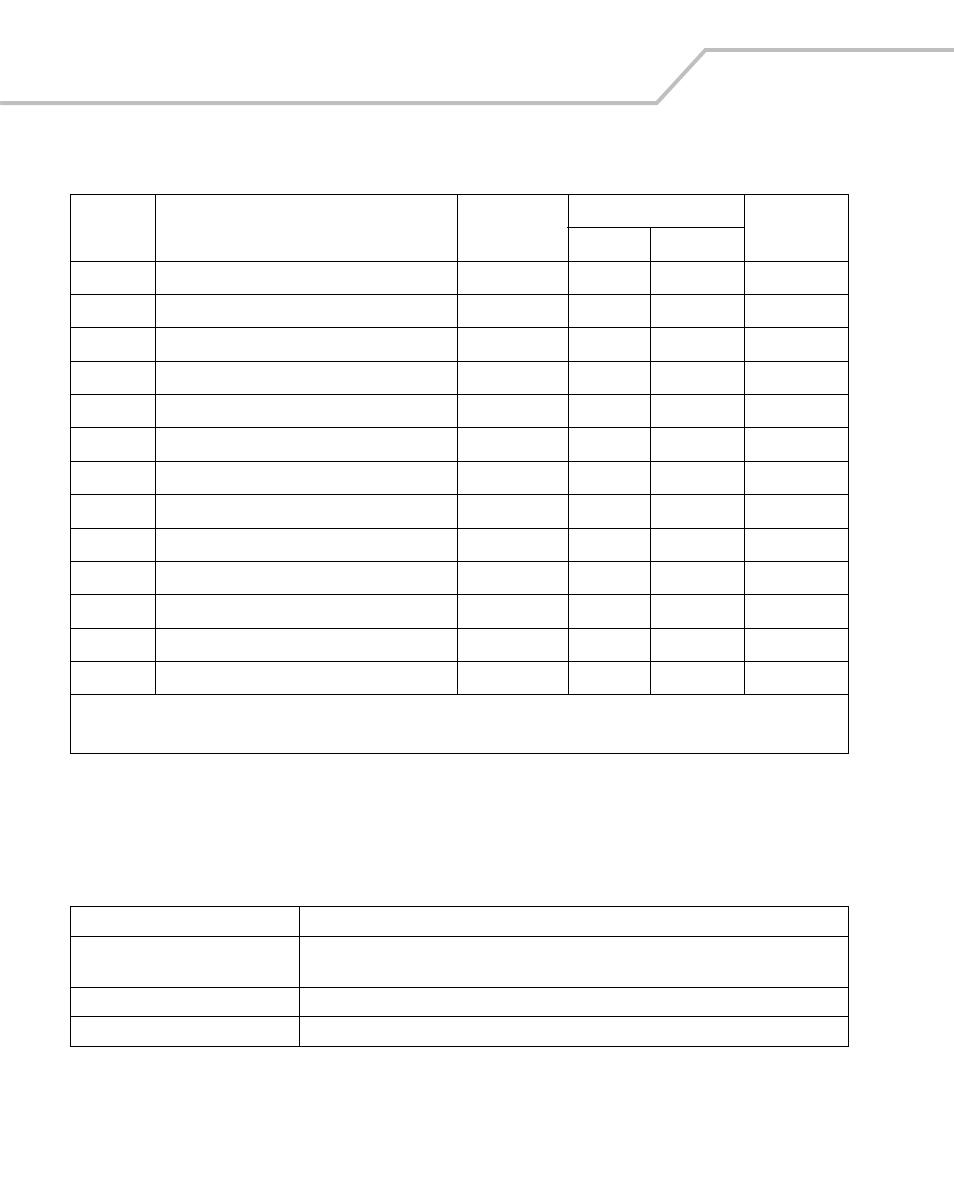
Page 318: Table 7-5. s-register settings (continued)
MC9000-G Product Reference Guide for Embedded Windows® CE .NET
7-42
Modem LED Indicators
S31
General Bit Mapped Options Status
-
195 (C0h)
S36
LAPM Failure Control
-
7
*
S38
Delay Before Forced Hangup
0-255
20
S
S39
Flow Control Bit Mapped Options Status
-
3
S40
General Bit Mapped Options Status
-
104 (68h)
*
S41
General Bit Mapped Options Status
-
195 (C3h)
*
S46
Data Compression Control
-
138
*
S48
V.42 Negotiation Control
-
7
S86
Call Failure Indication
0-26
0
S91
PSTN Transmit Attenuation Level
0-15
10**
dBm
S92
Fax Transmit Attenuation Level
0-15
10**
dBm
S95
Extended Result Codes Control
0
*
S210
V.34 Symbol Rate
0-255
13 (0Dh)
Table 7-6. Modem LED Indicators
LED
Indication
Off
Modem is not properly connected to the mobile computer; modem is not receiving
power.
Green
Modem is connected to the mobile computer and is receiving power.
Solid Amber
Mobile computer is communicating with the host computer.
Table 7-5. S-Register Settings (Continued)
Reg
Function
Range
Default
Units
De-fault
Saved
* Register value may be stored in on of two user
** Country-dependent