1 standard connection example, Signals and wiring – MITSUBISHI ELECTRIC MR-J2S- CP User Manual
Page 51
3 - 2
3. SIGNALS AND WIRING
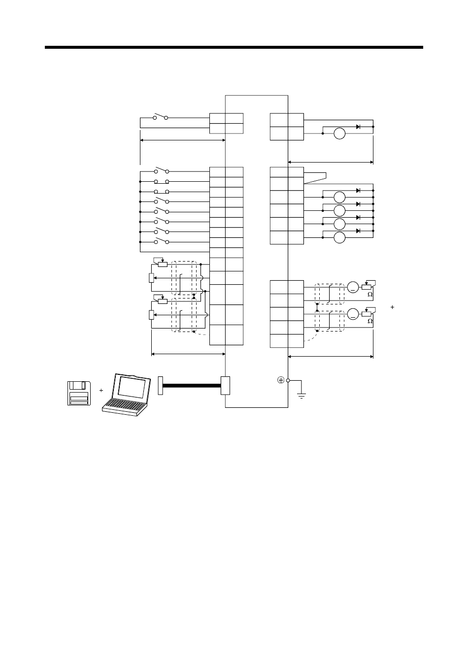
3.1 Standard connection example
Servo amplifier
(Note 3, 7) (Note 3, 7)
CN1A
CN1A
DOG
SG
8
10
9
18
COM
ZP
(Note 3, 7) (Note 3, 7)
CN1B
CN1B
15
16
17
7
5
14
8
9
10
11
2
1
12
Plate
SON
LSP
LSN
MD0
DI0
DI1
ST1
ST2
SG
P15R
VC
LG
TLA
SD
3
13
4
6
18
19
VDD
COM
CPO
MEND
ALM
RD
(Note 3, 7)
CN3
4
3
14
13
Plate
MO1
LG
MO2
LG
SD
CN3
10m (32.79ft.) or less
Proximity dog
Servo-on
Forward rotation stroke end
Reverse rotation stroke end
Automatic/manual selection
Point table No. selection 1
Point table No. selection 2
Forward rotation start
Reverse rotation start
(Note 5)
Upper limit setting
Upper limit setting
(Note 8) Override
(Note 9) Analog torque limit
2m (6.56ft.) or less
(Note 11)
Personal
computer
MR Configurator
(Servo Configuration
software)
(Note 10)
Communication cable
(Note 1)
2m (6.56ft.) or less
A
A
10k
10k
(Note 10)
Monitor output
Max. 1mA
meter
Zero center
(Note 4)
RA5
(Note 2, 4)
RA1
RA2
RA3
RA4
Rough match
Movement finish
Trouble (Note 6)
Ready
Home position
return completion
10m (32.81ft.) or less
(Note 12)
Note 1. To prevent an electric shock, always connect the protective earth (PE) terminal of the servo amplifier to the protective earth
(PE) of the control box.
2. Connect the diode in the correct direction. If it is connected reversely, the servo amplifier will be faulty and will not output
signals, disabling the forced stop and other protective circuits.
3. CN1A, CN1B, CN2 and CN3 have the same shape. Wrong connection of the connectors will lead to a fault.
4. The sum of currents that flow in the external relays should be 80mA max. If it exceeds 80mA, supply interface power from
external.
5. When starting operation, always connect the forward/reverse rotation stroke end (LSN/LSP) with SG. (Normally closed
contacts)
6. Trouble (ALM) is connected with COM in normal alarm-free condition.
7. The pins with the same signal name are connected in the servo amplifier.
8. When using override (VC), make the override selection (OVR) device available.
9. When using analog torque limit (TLA), make the external torque limit selection (TL) devices available.
10. When connecting the personal computer together with monitor outputs 1, 2, use the maintenance junction card (MR-
J2CN3TM). (Refer to section 14.1.6).
11. Use MRZJW3-SETUP 151E.
12. When using the internal power supply (VDD), always connect VDD-COM. Do not connect them when supplying external
power. Refer to section 3.6.2.