Handle, rear, and connector block – Sony DT 11-18mm f/4.5-5.6 Lens User Manual
Page 7
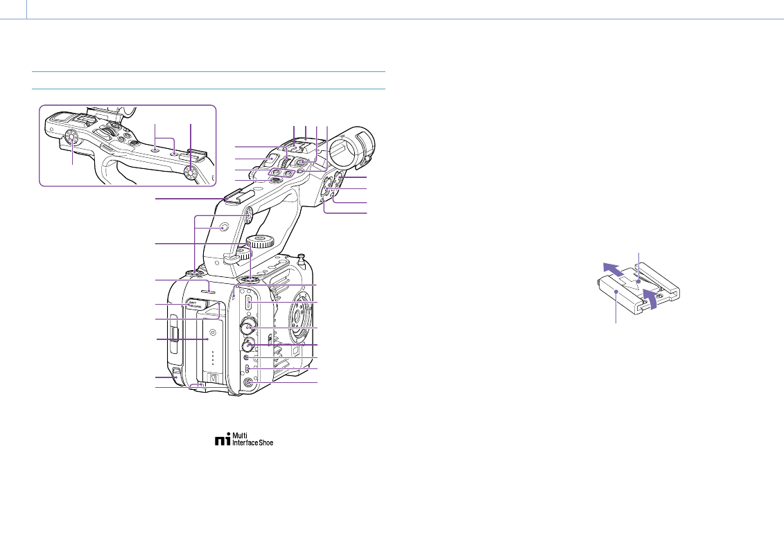
1. Overview: Location and Function of Parts
7
Handle, Rear, and Connector Block
11
10
8
7
6
5
4 3 2 1
21
16
10
10
10
9
17
18
19
22
23
20
24
25
26
14
13
12
15
20
1.
Handle HOLD switch
Use to disable operation of the controls on the
handle.
2.
Handle record START/STOP button
3.
Handle internal microphone
4.
Multi-interface shoe
For details about accessories supported by
the multi-interface shoe, contact your sales
representative.
5.
Handle assignable dial (page 48)
6.
Handle zoom lever (page 93)
7.
ASSIGN (assignable) 7 to 8 buttons
(page 48)
8.
Multi selector (8-way D-pad and apply
buttons)
9.
10.
Accessory attachment screw holes
(1/4 inch)
Compatible with 1/4-20 UNC screws (length of
6 mm or less).
[Note]
Use of screws longer than 6 mm may damage the
exterior surface.
11.
Recording/tally lamp (rear) (page 34)
12.
BATT RELEASE button (page 17)
13.
Air inlet
[Note]
Do not cover the air inlet.
14.
Battery pack attachment (page 17)
15.
USB-C connector (page 60)
16.
INPUT2 (audio input 2) connector
(page 46)
17.
INPUT1 (audio input 1) connector
(page 46)
18.
INPUT2 (LINE/MIC/MIC+48V) switch
(page 46)
19.
INPUT1 (LINE/MIC/MIC+48V) switch
(page 46)
20.
Screw holes for external devices
Compatible with M3 screws (length of 4 mm
or less).
[Note]
Use of screws longer than 4 mm may damage the
exterior surface.
21.
HDMI OUT connector (page 106)
22.
SDI OUT connector (page 106)
23.
TC IN/TC OUT (timecode input/output)
connector (page 107)
24.
REMOTE connector
Connect to general-purpose LANC jack
accessory.
25.
USB/multi connector (page 108)
26.
DC-IN connector (standard DC jack)
(page 18)
Attaching the accessory shoe
1
Lift the front edge of the shoe spring, and
pull the spring in the opposite direction to
the arrow engraved on the spring.
Shoe spring
Accessory shoe
1
2
Position the accessory shoe on the
accessory shoe mount, aligning the
protrusions on the shoe with the
corresponding points on the mount, and
tighten the four screws.