Xfcch4.pdf, 2 communication ports – Emerson Process Management ControlWave XFC User Manual
Page 89
CI-ControlWave XFC
Specifications / 4-1
Section 4
SPECIFICATIONS
4.1 CPU, MEMORY & PROGRAM INTERFACE
Processor:
Sharp’s LH7A400 32-bit System-on-Chip with 32-bit
ARM9TDMI RISC Core
Memory:
8 Mbytes of simultaneous read/write FLASH
2 Mbyte of on-board SRAM
512 Kbytes FLASH Boot/Downloader
Real Time Clock:
Contained in SC520 - generates a 1-second timer
pulse for use by the application software.
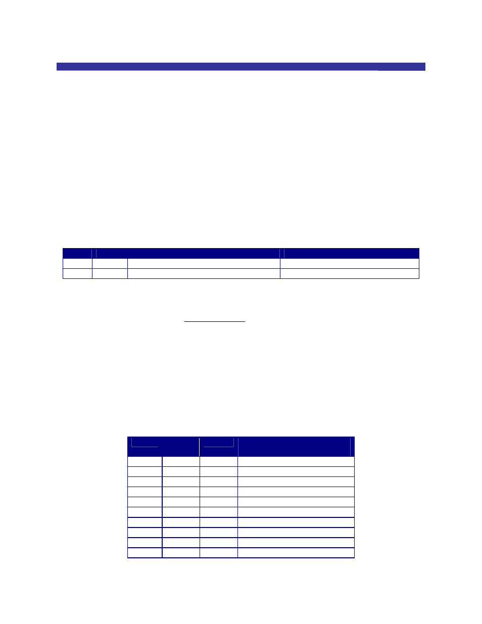
Connectors:
(see Table 4-1 and referenced Tables)
Table 4-1 - CPU Board Connector Summary
Ref. # Pins
Function
Notes
P1
86-pin
Factory Test ONLY
P2
26-pin
I/O, Comm. & Power Interface
To/from I/O Board
4.2 COMMUNICATION PORTS
Connector/Port: Terminal
Plate
COM1 - RS-232 (Term Block - J2-5 through J2-7)
COM2 - RS-232 (Term Block - J2-8 through J2-14)
COM3 - RS-485 (Term Block - J2-1 through J2-4)
Baud Rate:
300 to 115Kbps for RS-232
300 to 38.4Kbps for RS-485
Terminations:
Pluggable, maximum wire size is 16 gauge
Table 4-2 - RS-232 Port (COM1/2) Pin Assignments
Pin #
Signal
RS-232
Port #t
Description:
RS-232 Signals
J2-5
RXD
COM1
Receive Data Input
J2-6
TXD
COM1
Transmit Data Output
J2-7 GND COM1 Signal/Power
Ground
J2-8
TXD
COM2
Transmit Data Output
J2-9
RXD
COM2
Receive Data Input
J2-10 RTS
COM2
Request To Send Output
J2-11 CTS
COM2
Clear To Send Input
J2-12 DTR
COM2
Data Terminal Ready Output
J2-13 DCD
COM2
Data Carrier Detect Input
J2-14 GND COM2 Signal/Power
Ground