Emerson Process Management ControlWave XFC User Manual
Page 17
CI-ControlWave XFC
Introduction / 1-3
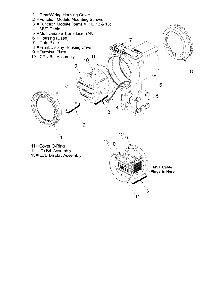
Figure 1-2 - ControlWave XFC (Isometric Views)
Component Identification Diagram (Shown with MVT)
The I/O Board contains I/O field interface circuitry and non-isolated power circuitry. Non-
isolated power is generated and regulated by the I/O Board that provides +3.6Vdc for all
logic and bulk power for I/O field circuits from a bulk source of +6Vdc to +30Vdc.
Additionally, the I/O Board provides 3.3Vdc (logic power) to the CPU Board. +1.8Vdc, used
by the ARM microprocessor, is generated on the CPU Board (derived from the 3.3Vdc).
1.2 ControlWave PROGRAMMING ENVIRONMENT
ControlWave programming environment uses industry-standard tools and protocols to
provide a flexible, adaptable approach for various process control applications in the gas,
water treatment, wastewater treatment, and industrial automation business.