Emerson Process Management ControlWave XFC User Manual
Page 64
2-22 / Installation & Operation
CI-ControlWave XFC
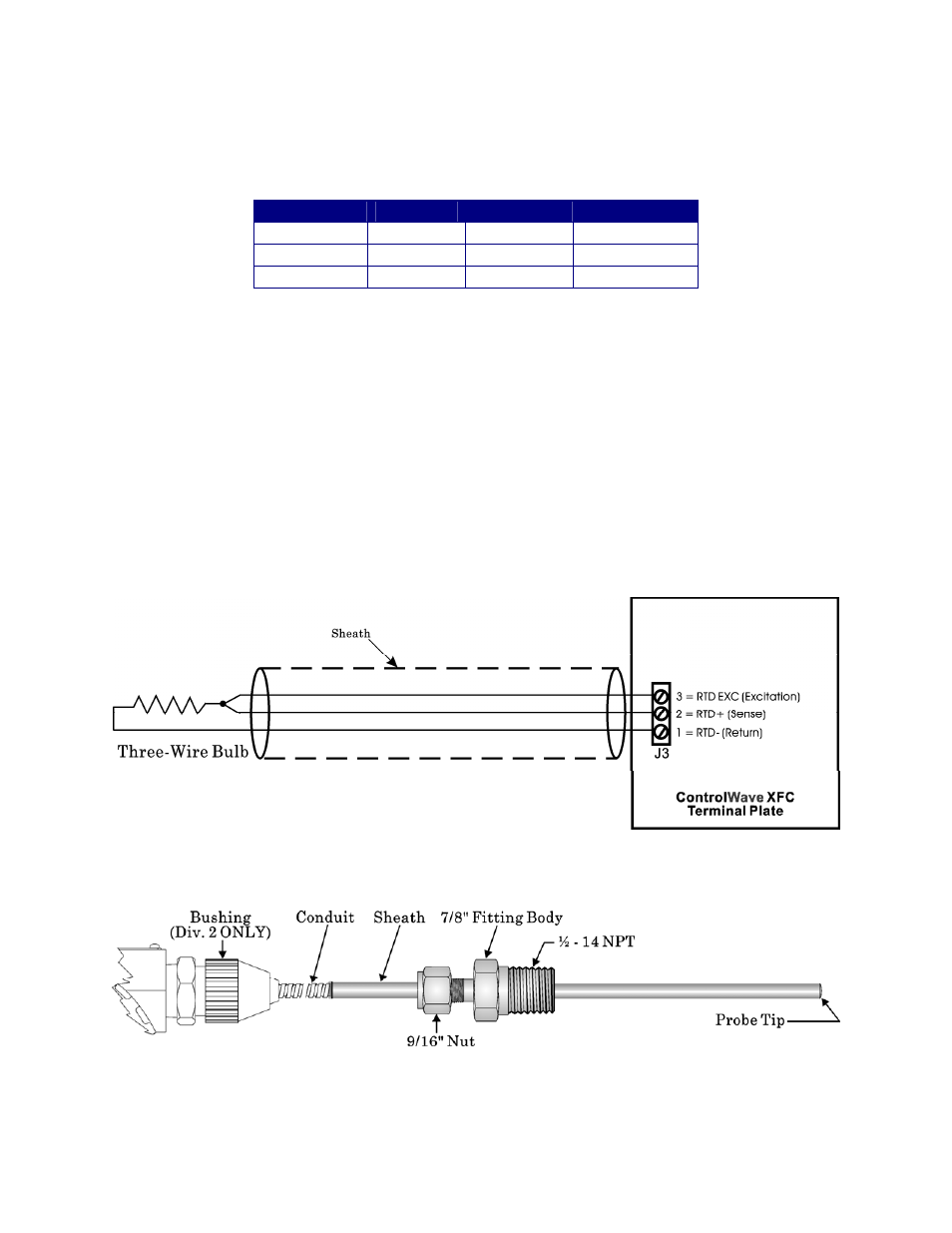
ControlWave XFC’s utilize the common three-wire con-figuration. In this configuration,
the Return lead connects to RTD- and the two junction leads (Sense and Excitation),
connect to RTD+ and RTD EXC. Connection between the RTD and System Controller
Module is wired as follows:
Table 2-4- RTD Connections to Terminal Plate Connector J3
J3 Pin #
Signal
Function
Wire Color
3 RTD
EXC
Excitation
Red
2 RTD+ Sense Red
1 RTD- Return White
Never ground the RTD Cable Shield at both ends or allow it to come in contact with metal-
lic/conductive conduit as multiple ground paths could cause RTD input errors.
2.3.4.1 Bendable RTD Installation
WARNING: ONLY use a bendable RTD (supplied with a plastic bushing) for
Division 2 installations, as this will render the Housing Non-Explosion Proof. Use
an RTD Connection Head and Conduit for Division 1 installations.
To install the RTD Probe, screw the Fitting Body into the thermowell with a 7/8”open-end
wrench. While applying pressure against the sheath to force the Tip of the RTD Probe into
the bottom of the thermowell (so that the Probe Tip is in contact with the thermowell),
tighten the Nut (9/16” open-end wrench) against the 7/8” Fitting Body (see Figure 2-12).
Figure 2-11 - 3-Wire RTD Temperature Input Wiring
Figure 2-12 - RTD Probe Installation/Removal Diagram