Front, Rear, Ci-controlwave xfc installation & operation / 2-15 – Emerson Process Management ControlWave XFC User Manual
Page 57
CI-ControlWave XFC
Installation & Operation / 2-15
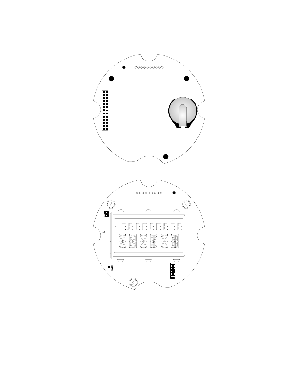
updumps. Local Mode is used for normal operation. When both SW1-9 and SW1-10 are set
ON or OFF, or with SW1-9 set ON and SW1-10 set OFF, Recovery Mode is enabled. Local
Mode is enabled when SW1-9 is OFF and SW1-10 is ON.
1
2
BT1
P2
JP1
CR2
CR1
IDLE
WD
LCD
Contrast
SW1
R43
ON
1
234
5
6
7
89
1
0
1
2
3
4
5
6
7
8
9
10
Battery
Backup
General
Purpose
DIP
Switch
FRONT
Note: Connectors not shown are for Factory Use ONLY!
REAR
Figure 2-8 - CPU Module Component Identification Diagram
2.3.2.2 Communication Ports
A ControlWave XFC can be configured as a Master or Slave node on either a MODBUS
network or a BSAP network. A variety of communication schemes are available. Three
communication ports are available and are accessible on the Wiring Plate Assembly. These
communication ports are designated as follows: