B.1 parameter table – Yaskawa J1000 Compact Vector Control Drive User Manual
Page 209

No.
Name
Description
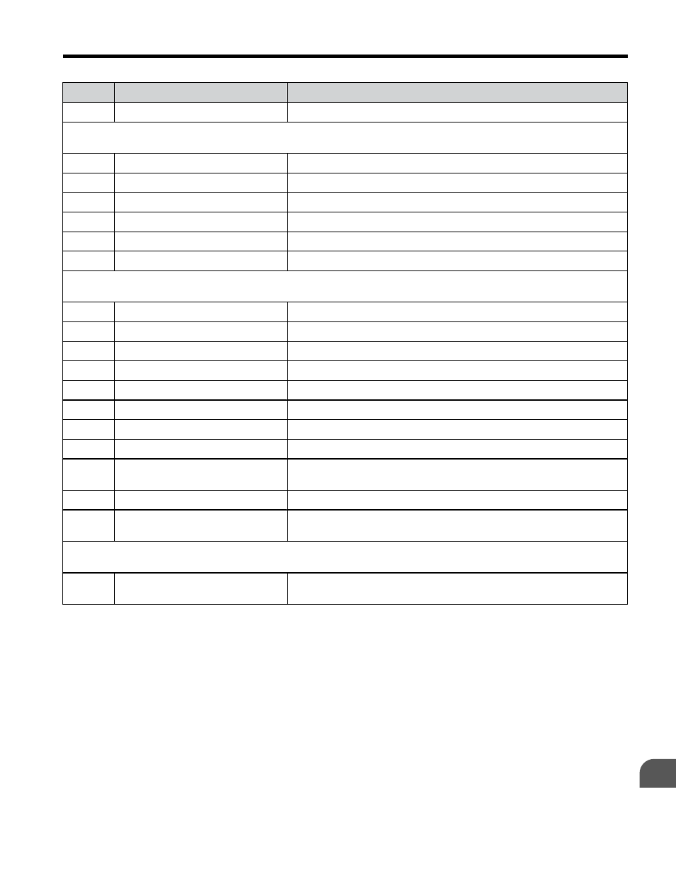
U4-23 Option Card Reference
Refer to V1000 Technical Manual for details.
U5: PID Monitor
Use U5 parameters to view application-specific settings.
U5-01 PID Feedback
Displays the PID feedback value.
U5-02 PID Input
Refer to V1000 Technical Manual for details.
U5-03 PID Output
Displays PID control output.
U5-04 PID Setpoint
Displays the PID setpoint.
U5-05 PID differential feedback
Refer to V1000 Technical Manual for details.
U5-06 PID Adjusted Feedback
Refer to V1000 Technical Manual for details.
U6: Control Monitor
Use U6 parameters to display drive control information.
U6-01 Motor Secondary Current (Iq)
Refer to V1000 Technical Manual for details.
U6-02 Motor Excitation Current (ld)
Refer to V1000 Technical Manual for details.
U6-03 ASR Input
Refer to V1000 Technical Manual for details.
U6-04 ASR Output
Refer to V1000 Technical Manual for details.
U6-05 Output voltage reference (Vq)
Output voltage reference (Vq). (q-axis)
U6-06 Output Voltage Reference (Vd)
Output voltage reference (Vd). (d-axis)
U6-07 q-axis ACR Output
Refer to V1000 Technical Manual for details.
U6-08 d-Axis ACR Output
Refer to V1000 Technical Manual for details.
U6-20 Frequency Reference Bias (Up/
Down 2)
Refer to V1000 Technical Manual for details.
U6-21 Offset Frequency
Refer to V1000 Technical Manual for details.
U6-80 to
U6-99
Option Monitors 1 to 20
Refer to the V1000 Option Technical Manual for details.
U8: Custom Monitors for DriveWorksEZ
U8 monitors are reserved for DriveWorksEZ
U8-01 to
U8-10
DWEZ Monitors 1 to 10
Refer to the V1000 Option Technical Manual for details.
Note:
1. Cycle power to the drive to enable MEMOBUS/Modbus settings.
2. If using Open Loop Vector Control (A1-02 = 2), Auto-Tuning will need to be performed again after
Refer to Auto-Tuning on page 113
B.1 Parameter Table
YASKAWA ELECTRIC TOEP C710606 47C YASKAWA AC Drive – V1000 Quick Start Guide
209
B
Parameter List
