6 three-dimensional tool compensation (option 9), Introduction, Three-dimensional tool compensation (option 9) – HEIDENHAIN TNC 620 (81760x-02) User Manual
Page 450
Programming: Multiple axis machining
12.6 Three-dimensional tool compensation (option 9)
12
450
TNC 620 | User's Manual
HEIDENHAIN Conversational Programming | 2/2015
12.6
Three-dimensional tool
compensation (option 9)
Introduction
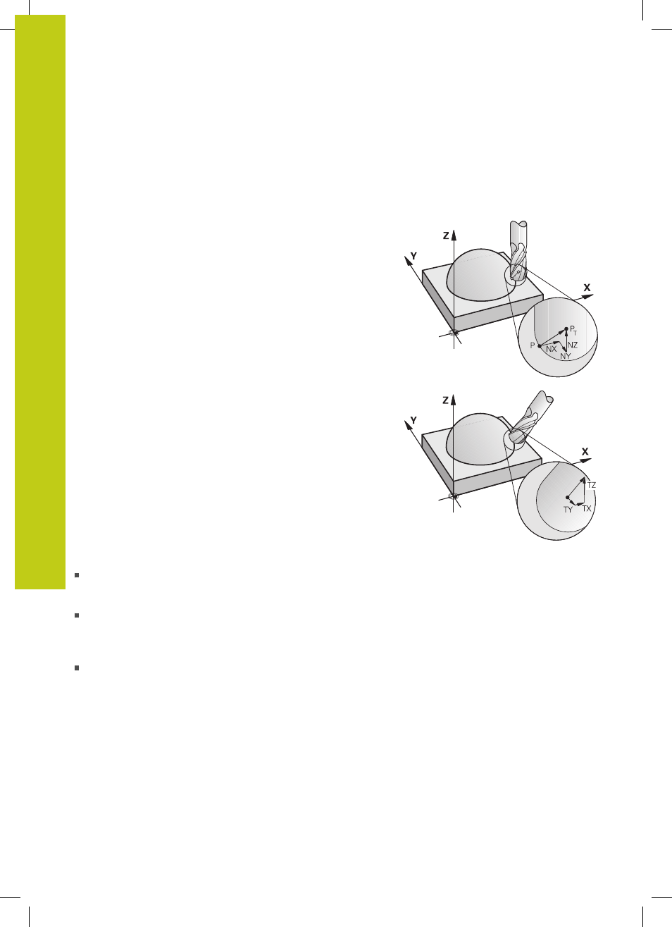
The TNC can carry out a three-dimensional tool compensation (3-
D compensation) for straight-line blocks. Apart from the X, Y and Z
coordinates of the straight-line end point, these blocks must also
contain the components NX, NY and NZ of the surface-normal
vector see "Definition of a normalized vector", page 451.
If you want to carry out a tool orientation, these blocks need also
a normalized vector with the components TX, TY and TZ, which
determines the tool orientation, see "Definition of a normalized
vector", page 451.
The straight-line end point, the components for the surface-normal
vector as well as those for the tool orientation must be calculated
by a CAM system.
Application possibilities
Use of tools with dimensions that do not correspond with the
dimensions calculated by the CAM system (3-D compensation
without definition of the tool orientation).
Face milling: compensation of the cutter geometry in the
direction of the surface-normal vector (3-D compensation with
and without definition of the tool orientation). Cutting is usually
with the end face of the tool.
Peripheral milling: compensation of the cutter radius
perpendicular to the direction of movement and perpendicular to
the tool direction (3D radius compensation with definition of the
tool orientation). Cutting is usually with the lateral surface of the
tool.