Connecting the console port to the terminal – H3C Technologies H3C S10500 Series Switches User Manual
Page 46
36
RJ-45 pin Signal
DB-9 pin
Signal
6 RXD
3 TXD
7 DSR
4 DTR
8 CTS
7 RTS
•
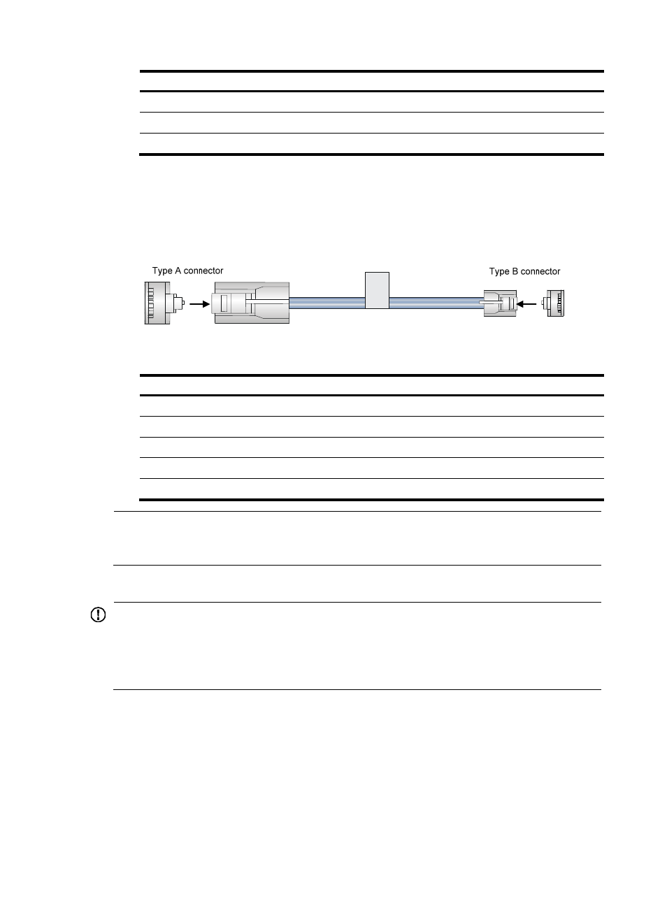
Console cable connecting the USB console port on a switch and the USB port on a terminal
The console cable has one mini-USB A/B connector for connecting to the USB console port on the
switch and one USB A connector for connecting to the USB port on the terminal.
shows the console cable and
shows its pinouts.
Figure 38 Console cable connecting the USB port and the USB console port
Table 9 Pinouts for the console cable connecting the USB port and the USB console port
USB A pin
Signal
mini-USB A/B pin
Signal
1 VBUS
1
VBUS
2 D-
2
D-
3 D+
3
D+
4
ID(NC)
4 GND
5
GND
NOTE:
If two MPUs are installed on a switch, you can use the console or USB console port on either of the MPU
for connecting a terminal.
Connecting the console port to the terminal
IMPORTANT:
•
Identify the mark on the console and USB console port and make sure you are connecting to the correct
port.
•
The serial ports on PCs do not support hot swapping. To connect a PC to an operating device, first
connect the PC end. To disconnect a PC from an operating device, first disconnect the device end.
To connect the console cable to the console port:
1.
Connect the DB-9 connector of the console cable to the serial port on a PC or terminal.
2.
Connect the RJ-45 connector of the console cable to the console port on the MPU of the switch.
To connect the console cable to the USB console port:
1.
Connect the USB-A connector of the console cable to the USB port on a PC or terminal.
2.
Connect the mini-USB A/B connector of the console cable to the USB console port on the MPU of
the switch.