H3C Technologies H3C S10500 Series Switches User Manual
Page 38
28
3.
Install a PoE PEM in the slot and fasten the captive screws.
4.
Connect the ring terminal marked with + of the black power cord to the power terminal marked
with RTN(+) on the PoE PEM:
a.
Remove the outer nut, spring washer, and flat washer from the power terminal.
b.
Connect the ring terminal to the power terminal.
c.
Install the flat washer, spring washer, and nut.
5.
Connect the ring terminal marked with – of the blue power cord to the power terminal marked with
NEG(–) on the PoE PEM. The process is the same as step 4.
6.
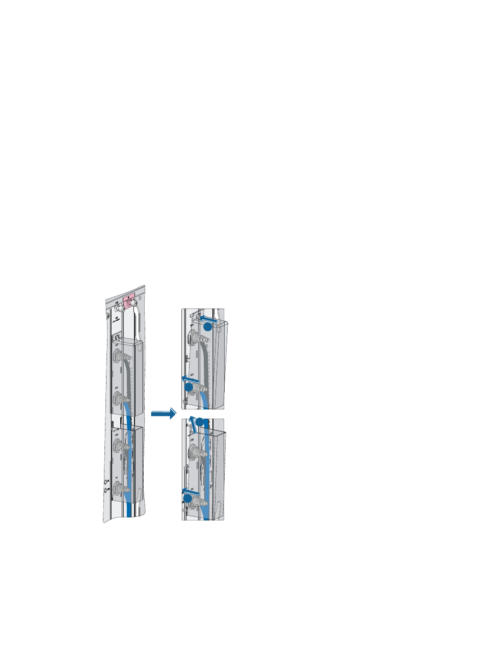
Install the terminal block cover over the power terminals, as shown in
To install the terminal block cover for an S10506 switch or the upper terminal block cover for an
S10510 switch:
a.
Insert the locking tabs on the terminal block cover into the holes in the terminal block.
b.
Press the terminal block cover until the cover is securely seated.
To install the lower terminal block cover for an S10510 switch:
a.
Insert the locking tabs on the terminal block cover into the holes in the terminal block.
b.
Press and push the terminal block cover upward until the cover is securely seated.
Figure 26 Installing the upper and lower terminal block covers over the power terminals (S10510)
7.
(Optional.) For an S10510 switch, repeat steps 1 to 6 to complete connection to another pair of
power terminals. Make sure the upper pair of power cords are covered by both terminal block
covers.
8.
Use cable ties to secure the power cords to the cable hangers over the air vent section. For more
information about how to use a cable tie, see
3
4
2
1