H3C Technologies H3C S10500 Series Switches User Manual
Page 15
5
•
The rack for the switch has a good cooling system.
•
The installation site has a good cooling system.
•
Verify that the airflow design for the chassis meets the airflow design of the installation site.
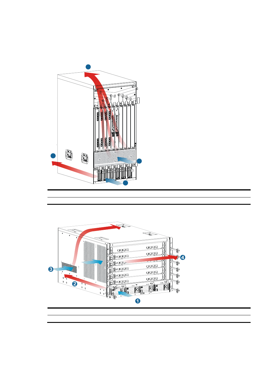
Figure 1 Airflow through the S10508-V chassis
(1) Power module air inlet vents
(2) Power module air outlet vents
(3) Chassis air inlet vents (4)
Chassis air outlet vents
Figure 2 Airflow through other S10500 switch chassis (S10506)
(1) Power module air inlet vents
(2) Power module air outlet vents
(3) Chassis air inlet vents
(4) Chassis air outlet vents
2
4
1
3
See also other documents in the category H3C Technologies Routers:
- H3C S12500X-AF Series Switches (3 pages)
- H3C S12500X-AF Series Switches (3 pages)
- H3C S12500X-AF Series Switches (53 pages)
- H3C S12500 Series Switches (19 pages)
- H3C MSV 50 (8 pages)
- H3C S12500 Series Switches (21 pages)
- H3C S9500E Series Switches (4 pages)
- H3C S7500E Series Switches (3 pages)
- H3C WA2200 Series WLAN Access Points (42 pages)
- H3C S12500-X Series Switches (8 pages)
- H3C SR6600 (64 pages)
- H3C S9500E Series Switches (36 pages)
- H3C WA3600 Series Access Points (237 pages)
- H3C S9500E Series Switches (270 pages)
- H3C MSR 900 (249 pages)
- H3C S12500 Series Switches (163 pages)
- H3C S12500 Series Switches (170 pages)
- H3C MSR 900 (96 pages)
- H3C MSR 900 (443 pages)
- H3C MSR 900 (468 pages)
- H3C S9500E Series Switches (32 pages)
- H3C S9500E Series Switches (241 pages)
- H3C S12500 Series Switches (39 pages)
- H3C S6800 Series Switches (59 pages)
- H3C LSBM1WCM2A0 Access Controller Module (197 pages)
- H3C S10500 Series Switches (27 pages)
- H3C LSBM1WCM2A0 Access Controller Module (226 pages)
- H3C S6300 Series Switches (188 pages)
- H3C MSR 900 (410 pages)
- H3C MSR 900 (239 pages)
- H3C WA3600 Series Access Points (394 pages)
- H3C S10500 Series Switches (2 pages)
- H3C S10500 Series Switches (2 pages)
- H3C S10500 Series Switches (2 pages)
- H3C S10500 Series Switches (2 pages)
- H3C S10500 Series Switches (2 pages)
- H3C S10500 Series Switches (2 pages)
- H3C S10500 Series Switches (2 pages)
- H3C S10500 Series Switches (1 page)
- H3C S7500E Series Switches (19 pages)
- H3C S7500E Series Switches (115 pages)
- H3C S6300 Series Switches (58 pages)
- H3C S6300 Series Switches (208 pages)
- H3C S6300 Series Switches (251 pages)