Current pin status, Dtr alarm control and status table – Verilink WANsuite 5370 (34-00310.D) Product Manual User Manual
Page 40
3-10
W A N s u i t e 5 3 7 0
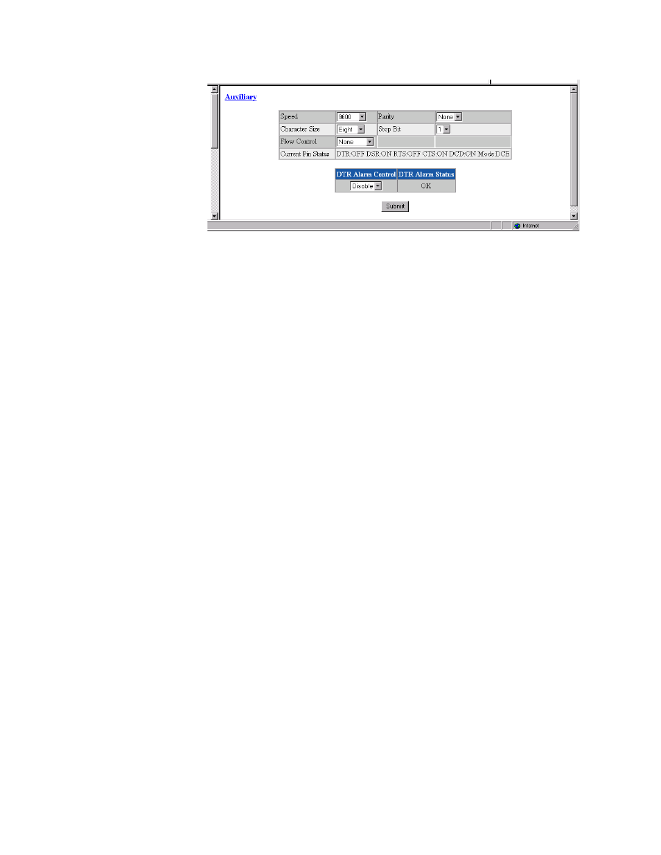
Figure 3.6
Auxiliary Screen
Speed
Changes the Auxiliary port speed (in bits per second).
Values: 1200, 2400, 4800, 9600, 19200, 38400, 57600, 115200
Default: 9600
Character Size
Selects the number of bits required to make up one asynchronous character.
Values: Five, Six, Seven, Eight
Default: Eight
Flow Control
Selects the type of flow control to be used if the port is asynchronous.
Values: None, Xon/Xoff, RTS/CTS
Default: None
Parity
Sets the parity bit if the port is asynchronous.
Values: None, Odd, Even
Default: None
Stop Bit
Selects the number of bits required to end the character.
Values: 1, 2
Default: 1
Current Pin Status
The Current Pin Status, which shows the state of the RS-232 pins, is also
displayed on the Auxiliary interface screen.
DTR Alarm Control and Status Table
In addition to the configurable fields, the Auxiliary screen displays a table
that lets you set the Data Terminal Ready (DTR) Alarm Control parameters
and view the current DTR Alarm Status.
Choices for DTR Alarm Control are “Enable” and “Disable”; the default
setting is “Disable.” Setting DTR Alarm Control to “Enable” allows the unit
to go into alarm on a loss of DTR. The DTR Status field indicates the current
state of the DTR alarm.