Configuration of the 195 dmm, Taking readings – Measurement Computing Personal488 rev.3.0 For DOS & Windows 3.Xi User Manual
Page 90
II. SOFTWARE GUIDES - 8. Driver488/DRV
8H. Turbo C
Personal488 User’s Manual, Rev. 3.0
II-75
It is not necessary to perform the
HELLO
command, but it is included here as a simple example of
normal communication with Driver488/DRV. Its response is the revision identification of the
Driver488/DRV software:
Driver488 Revision X.X ©199X IOtech, Inc.
We can also interrogate Driver488/DRV for its status:
ieeewt(“status\n”);
ieeerd(response);
printf(“%s\n”,response);
Subsequently, the printed response is similar to the following:
CS21 1 I000 000 T0 C0 P0 OK
Configuration of the 195 DMM
Once the system is initialized we are ready to start issuing bus commands. The IEEE 488 bus has
already been cleared by the Interface Clear (
IFC
) sent by the
RESET
command, so we know that all bus
devices are waiting for the controller to take some action. To control an IEEE 488 bus device, we
output an appropriate device-dependent command to that device. For example, the
F0R0X
command
line below sets the 195 to read DC volts with automatic range selection:
ieeewt(“output 16;F0R0X\n”);
The
OUTPUT
command takes a bus device address (
16
in this case) and data (
F0R0X
) and sends the data
to the specified device. The address can be just a primary address, such as
12
, or
05
, or it can include
a secondary address:
1201
. Note that both the primary address and, if present, the secondary address
are two-digit decimal numbers. A leading zero must be used, if necessary to make a two-digit address.
Taking Readings
Once we have set the 195’s operating mode, we can take a reading and display it:
float voltage;
ieeewt(“enter 16\n”);
ieeescnf(“%*4s%e”,&voltage);
printf(“The read value is %g\n”,voltage);
The
ENTER
command takes a bus address (with an optional secondary address) and configures that bus
device so that it is able to send data (addressed to talk). No data is actually transferred, however, until
the
IEEESCNF
statement requests the result from Driver488/DRV at which time data is transferred to
the program into the variable
voltage
. A typical reading from a 195 might be
NDCV+1.23456E-2
,
consisting of a four character prefix followed by a floating point value. The format passed to
IEEESCNF
causes it to skip the four character prefix (
%*4s
) and then convert the remaining string into
the float variable
voltage
.
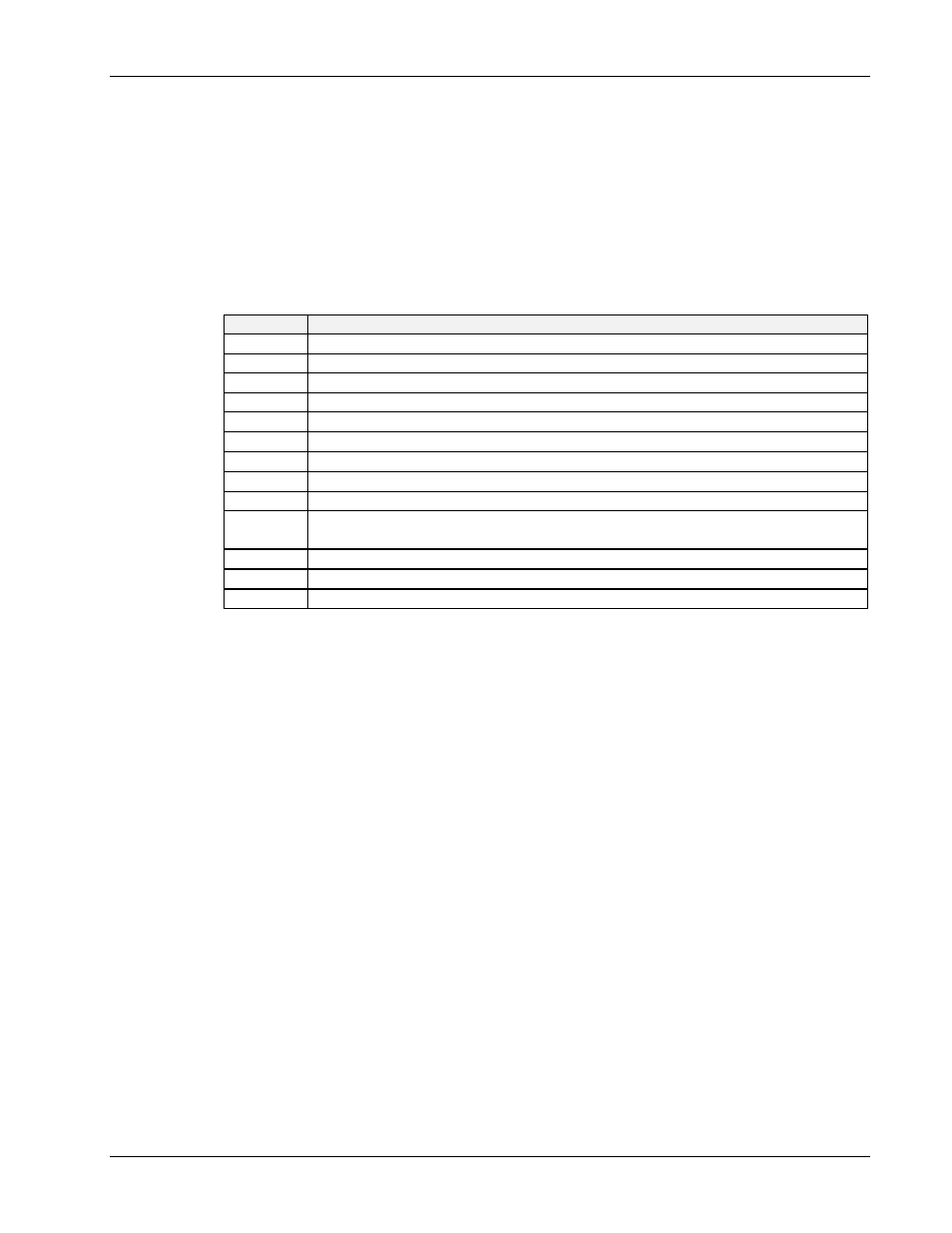
The following indicators describe each component of the Driver488/DRV status:
Indicator
Driver488/DRV Status
C
It is in the Controller state.
S
It is the System Controller.
21
The value of its IEEE 488 bus address.
1
An Address Change has occurred.
I
It is idle (neither a talker nor a listener).
0
There is no
ByteIn
available.
0
It is not ready to send a
ByteOut
.
0
Service Request (
SRQ
) is not asserted.
000
There is no outstanding error.
T0
It has not received a bus device
TRIGGER
command (only applicable in the Peripheral
mode).
C0
It has not received a
CLEAR
command (only applicable in the Peripheral mode).
P0
No
CONTINUE
transfer is in progress.
OK
The error message is “OK”.