Measurement Computing Personal488 rev.3.0 For DOS & Windows 3.Xi User Manual
Page 37
I. HARDWARE GUIDES
5. Personal488/MM
Personal488 User’s Manual, Rev. 3.0
I-21
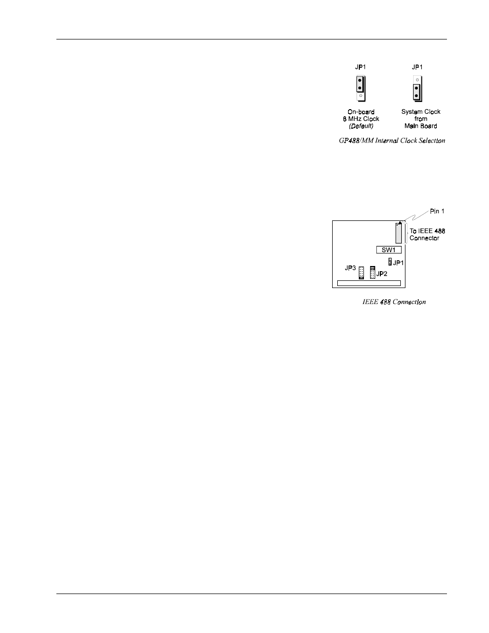
Internal Clock Selection
The IEEE 488 bus interface circuitry requires a master clock. This
clock is normally connected to an on-board 8 MHz clock oscillator.
However, some compatible IEEE 488 interface boards connect this
clock to the PC’s own clock signal. Using the PC clock to drive
the IEEE 488 bus clock is not recommended because the PC clock
frequency depends on the model of computer. A standard PC has a
4.77 MHz clock, while an AT might have a 6 MHz or 8 MHz
clock. Other manufacturers’ computers may have almost any
frequency clock. If you are using a software package designed for
an interface board (that derived its clock from the PC clock) and
you need to do the same to use GP488/MM with that particular
software, the clock source can be changed. However, the clock frequency must never be greater than 8
MHz, and clock frequency must be correctly entered in the Driver488 software.
Board Installation
IEEE 488 interface board(s) are installed into expansion slots
inside the PC’s system unit. PC/AT-compatible computers have
two types of expansion slots: 8-bit (with one card-edge
receptacle), and 16-bit (with two card-edge receptacles). Eight-
bit boards, such as the IEEE 488 interface boards, may be used
in either type of slot, 8- or 16-bit. Some machines may have
special 32-bit memory expansion slots which should not be used
for IEEE 488 interface boards.
Install each IEEE 488 interface board into the expansion slots as
follows: Ensure the PC is turned off and unplug the power cord.
Remove the cover mounting screws from the rear of the PC
system unit. Remove the system unit cover by sliding it forward and tilting it upward.
A rear panel opening is provided at the end of each expansion slot for mounting I/O connectors. If a
slot is unused, this opening is covered by a metal plate held in place with a screw. Remove this screw
and the cover plate from the desired expansion slot, saving the screw.
Insert the IEEE 488 interface board carefully into the expansion slot, fitting the IEEE 488 connector
through the rear panel opening, and inserting its card edge into the motherboard card edge receptacle.
With the board firmly in place, fix its mounting bracket to the rear panel, using the screw removed from
the cover plate.
Slide the system unit cover back on, re-attaching it with the screws. Plug the power cord in and turn on
the PC. If all is well, the system should boot normally. If not, carefully check that none of the I/O
addresses conflict with any other devices or boards. If you are not sure, contact your PC’s dealer or
manufacturer.