Configuration of ieee 488 external devices – Measurement Computing Personal488 rev.3.0 For DOS & Windows 3.Xi User Manual
Page 58
II. SOFTWARE GUIDES - 8. Driver488/DRV
8B. Installation & Configuration
Personal488 User’s Manual, Rev. 3.0
II-43
•
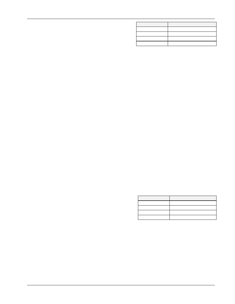
Interrupt: A hardware interrupt level can be
specified to improve the efficiency of the I/O
adapter control and communication using
Driver488/DRV. For any use of
OnEvent
and
Arm
functions, an interrupt level must be
selected. If no interrupt level is to be used,
select NONE. Valid interrupt levels depend
on the device type.
•
Input Buffer: This field is used to enter the buffer sizes for I/O.
•
Output Buffer: This field is used to enter the buffer sizes for I/O.
•
Parity: Parity can be EVEN, ODD, NONE, MARK, or SPACE.
•
CTS Timeout: The driver supports 3 hardware handshake lines: Data Carrier Detect (
DCD
), Data
Set Ready (
DSR
), and Clear To Send (
CTS
). Each line can be individually designated to be
ignored, used with no specified timeout, or used with a selected timeout. The timeout is selected
by specifying the number of milliseconds to wait for the indicated condition to become satisfied.
•
Data Bits: Data formats from 5 though 8 Data Bits are supported.
•
DSR Timeout: The driver supports 3 hardware handshake lines: Data Carrier Detect (
DCD
), Data
Set Ready (
DSR
), and Clear To Send (
CTS
). Each line can be individually designated to be
ignored, used with no specified timeout, or used with a selected timeout. The timeout is selected
by specifying the number of milliseconds to wait for the indicated condition to become satisfied.
•
Stop Bits: With 6, 7, or 8 Data Bits specified, either 1 or 2 Stop Bits are allowed. With 5 Data
Bits specified, 1 or 1.5 Stop Bits may be selected.
•
DCD Timeout: The driver supports 3 hardware handshake lines: Data Carrier Detect (
DCD
), Data
Set Ready (
DSR
), and Clear To Send (
CTS
). Each line can be individually designated to be
ignored, used with no specified timeout, or used with a selected timeout. The timeout is selected
by specifying the number of milliseconds to wait for the indicated condition to become satisfied.
•
Timeout (ms): The time out period is the amount of time that data transfers wait before assuming
that the device does not transfer data. If the time out period elapses while waiting to transfer data,
an error signal occurs. This field is the default timeout for any bus request or action, measured in
milliseconds. If no timeout is desired, the value may be set to zero.
•
Device Type: This field specifies the type of device represented by the serial external device
name selected.
•
I/O Address: The I/O Address is the
computer bus address for the board. It is set to
default values, as listed in the table, during the
initial installation. These values can be
changed, however, using the default address
values is recommended. Any conflict will be
noted by a pop up help screen.
•
Bus Terminators: The bus terminators specify the characters to be appended to data that is sent
to the external device, or mark the end of data that is received from the external device.
Configuration of IEEE 488 External Devices
Within your IEEE 488.2 application program, devices on the bus may be accessed by name. These
names must be created and configured with the
CONFIG
program, after you have configured your
interfaces.
The following figure displays the configuration screen of an external device named
DMM195
. When
configuring an IEEE interface, this screen can be accessed by selecting
Devices
.
I/O Comm.
Typical Interrupt Level
COM1
typically level 4
COM2
typically level 3
COM3
typically level 4 or 5
COM4
typically level 2 or 3
I/O Comm.
Default Address Values
COM1
typically address 3F8
COM2
typically address 2F8
COM3
typically address 3E8
COM4
typically address 2E8