Configuration of the 195 dmm – Measurement Computing Personal488 rev.3.0 For DOS & Windows 3.Xi User Manual
Page 100
II. SOFTWARE GUIDES - 8. Driver488/DRV
8I. Turbo Pascal
Personal488 User’s Manual, Rev. 3.0
II-85
Next, we can enable
SEQUENCE - NO DATA AVAILABLE
error detection by setting the
FILL
mode to
ERROR
:
Writeln(IeeeOut,’FILL ERROR’);
The
IOCTL
,
RESET
, and
FILL ERROR
statements are also included in the
IEEEIO
unit initialization
code.
Once everything is reset, we can test the communications and read the Driver488/DRV revision number
with the
HELLO
command:
VAR Response: STRING;
Writeln(IeeeOut,’HELLO’);
Readln(IeeeIn,Response);
Writeln(Response);
First we
Writeln
the
HELLO
command to
IeeeOut
, then we
Readln
the response from
IeeeIn
into
the character variable
Response
. Finally we display the response with a
Writeln
to the screen.
Because Turbo Pascal cannot both
Writeln
and
Readln
from the same text file, we use two different
files to communicate with Driver488/DRV.
Writeln
must reference the file opened for output (in
these examples,
IeeeOut
) and
Readln
must reference the file opened for input (
IeeeIn
). Attempting
to communicate with the wrong file (such as
Writeln(IeeeIn_)
) results in an error.
It is not necessary to perform the
HELLO
command, but it is included here as a simple example of
normal communication with Driver488/DRV. Its response is the revision identification of the
Driver488/DRV software:
Driver488 Revision X.X ©199X IOtech, Inc.
We can also interrogate Driver488/DRV for its status:
Writeln(IeeeOut,’STATUS’);
Readln(IeeeIn,Response);
Writeln(Response);
Subsequently, the printed response is similar to the following:
CS21 1 I000 000 T0 C0 P0 OK
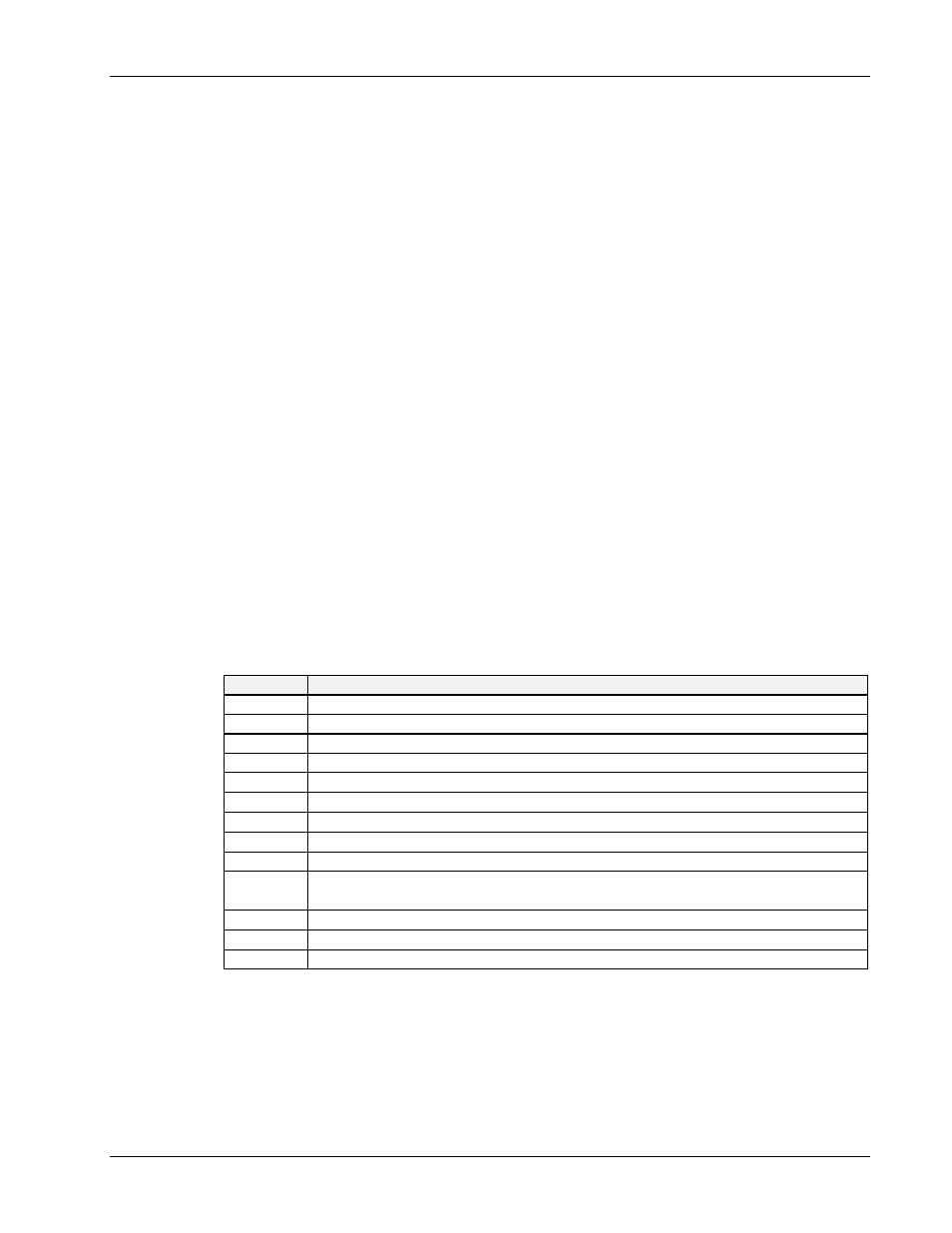
The following indicators describe each component of the Driver488/DRV status:
Indicator
Driver488/DRV Status
C
It is in the Controller state.
S
It is the System Controller.
21
The value of its IEEE 488 bus address.
1
An Address Change has occurred.
I
It is idle (neither a talker nor a listener).
0
There is no
ByteIn
available.
0
It is not ready to send a
ByteOut
.
0
Service Request (
SRQ
) is not asserted.
000
There is no outstanding error.
T0
It has not received a bus device
TRIGGER
command (only applicable in the Peripheral
mode).
C0
It has not received a
CLEAR
command (only applicable in the Peripheral mode).
P0
No
CONTINUE
transfer is in progress.
OK
The error message is “OK”.
Configuration of the 195 DMM
Once the system is initialized we are ready to start issuing bus commands. The IEEE 488 bus has
already been cleared by the Interface Clear (
IFC
) sent by the
RESET
command, so we know all bus
devices are waiting for the controller to take some action. To control an IEEE 488 bus device, we
OUTPUT
an appropriate device-dependent command to that device. For example, the command
F0R0X
sets the 195 to read DC volts with automatic range selection: