Measurement Computing Personal488 rev.3.0 For DOS & Windows 3.Xi User Manual
Page 153
9B. Installation & Configuration
II. SOFTWARE GUIDES - 9. Driver488/SUB
II-138
Personal488 User’s Manual, Rev. 3.0
Configuration Parameters
•
Name: This field is a descriptive instrument name which is manually assigned by the user. This
must be a unique name. Typically, IEEE or COM is used.
•
IEEE Bus Address: This is the setting for the IEEE bus address of the board. It will be checked
against all the instruments on the bus for conflicts. It must be a valid address from
0
to
30
.
•
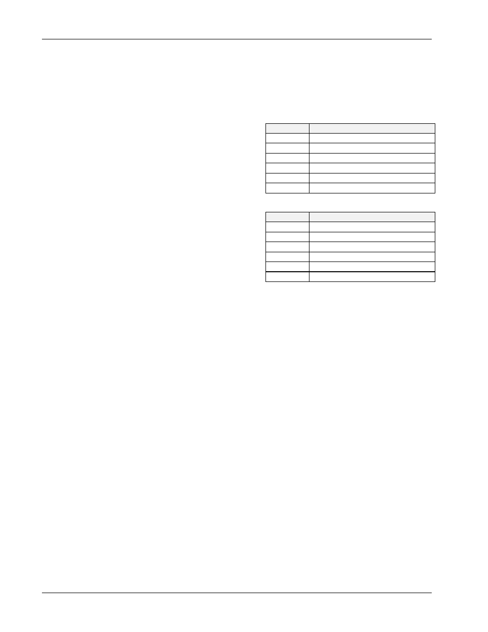
DMA: A direct memory access (DMA)
channel can be specified for use by the I/O
interface card. If DMA is to be used, select
a channel as per the hardware setting. If no
DMA is to be used, select NONE. The
NB488 does not support DMA, therefore the
DMA field will not display if this device
type is used. Valid settings are displayed in
the table.
•
Interrupt: A hardware interrupt level can
be specified to improve the efficiency of the
I/O adapter control and communication
using Driver488/SUB. For DMA operation
or any use of
OnEvent
and
Arm
functions,
an interrupt level must be selected. Boards
may share the same interrupt level. If no
interrupt level is to be used, select NONE.
Valid interrupt levels depend on the type of interface. Possible settings are shown in the table.
•
SysController: This field determines whether or not the IEEE 488 interface card is to be the
System Controller. The System Controller has ultimate control of the IEEE 488 bus, and the
ability of asserting the Interface Clear (
IFC
) and Remote Enable (
REN
) signals. Each IEEE 488
bus can have only one System Controller. If the board is a Peripheral, it may still take control of
the IEEE 488 bus if the Active Controller passes control to the board. The board may then control
the bus and, when it is done, pass control back to the System Controller or another computer,
which then becomes the active controller. If the board will be operating in Peripheral mode (not
System Controller), select NO in this field.
•
LightPen: This field determines whether the
LightPen
command is to be used. If selected, it
will disable the detection of interrupts via setting the light pen status. The default is light pen
interrupt enabled.
•
Timeout (ms): The time out period is the amount of time that data transfers wait before assuming
that the device does not transfer data. If the time out period elapses while waiting to transfer data,
an error signal occurs. This field is the default timeout for any bus request or action, measured in
milliseconds. If no timeout is desired, the value may be set to zero.
•
Device Type: This field specifies the type of board or module (such as GP488, MP488CT or
NB488) represented by the IEEE device name selected.
I/O Address
•
IEEE 488: This field is the I/O base address which sets the addresses used by the computer to
communicate with the IEEE interface hardware on the board. The address is specified in
hexadecimal and can be
02E1
,
22E1
,
42E1
or
62E1
.
Note: This field does not apply to the NB488. Instead, the NB488 uses the I/O address of the data
register (the first register) of the LPT port interface, typically
0x0378
.
•
Digital I/O: This field is the base address of the Digital I/O registers. It is only applicable for
MP488 and MP488CT boards. Note the Digital I/O SCPI communication parameters are
configured as an external device. Refer to the “Section I: Hardware Guides” for more information.
I/O Board
Specified DMA Channel
GP488B
1, 2, 3 or none
AT488
1, 2, 3, 5, 6, 7 or none
MP488
1, 2, 3, 5, 6, 7 or none
MP488CT
1, 2, 3, 5, 6, 7 or none
NB488
Not applicable
CARD488
Not applicable
I/O Board
Specified Interrupt Level
GP488B
levels 2-7 or none
AT488
levels 3-7, 9-12, 14-15 or none
MP488
levels 3-7, 9-12, 14-15 or none
MP488CT
levels 3-7, 9-12, 14-15 or none
NB488
level 7 for LPT1, level 5 for LPT2
CARD488
levels 3-7, 9-12, 14-15 or none